
Fluid damper

a damper and flue technology, applied in the direction of valve operating means/release devices, process and machine control, instruments, etc., can solve the problems of difficult control of airflow via prior art designs, loss of blade positioning or “set” often, and easy generation of noise by the “butterfly”

Inactive Publication Date: 2005-12-06
NAUGHTON BART
View PDF12 Cites 25 Cited by
  • Summary
  • Abstract
  • Description
  • Claims
  • Application Information

AI Technical Summary

Benefits of technology

[0021]It is therefore an object of the present invention to provide a fluid damper which very accurately controls the flow of air in a ventilation system.
[0028]Another object of the present invention is to provide a fluid damper which is easily mounted in a conventional duct.

Problems solved by technology

Unfortunately, these prior designs suffer from deficiencies in that positioning of the blades or “set” is often lost due to the flow of air against the blades.
Thus, the control of airflow via the prior art designs is difficult to achieve.
In addition, noise is easily generated by the “butterfly” and “split butterfly” designs.
These problems are exacerbated by flow rates of air required by clean room structures.

Method used


Image

  • Fluid damper
  • Fluid damper
  • Fluid damper

Examples


Embodiment Construction

[0043]Various aspects of the present invention will evolve from the following detailed description of the preferred embodiments thereof which may be fully understood by reference to the herein above-delineated drawings.

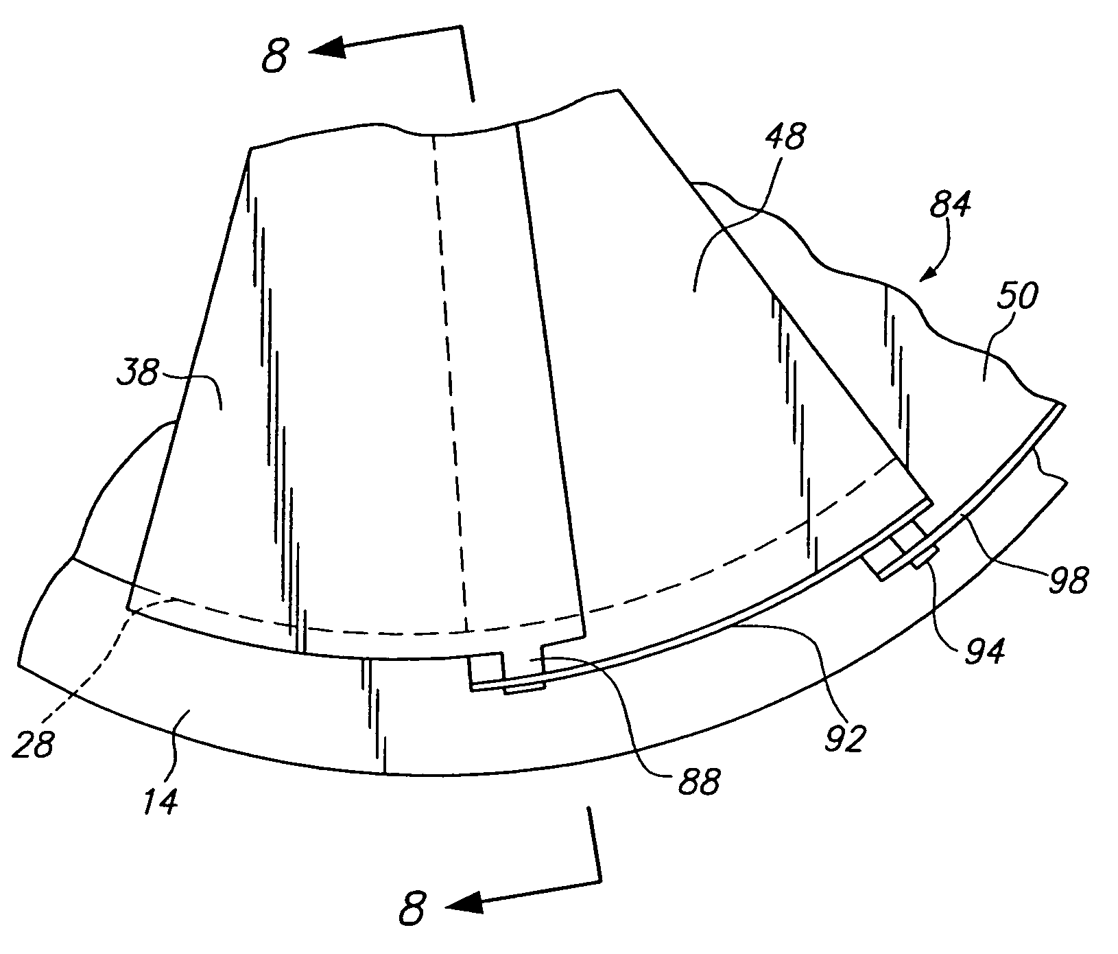
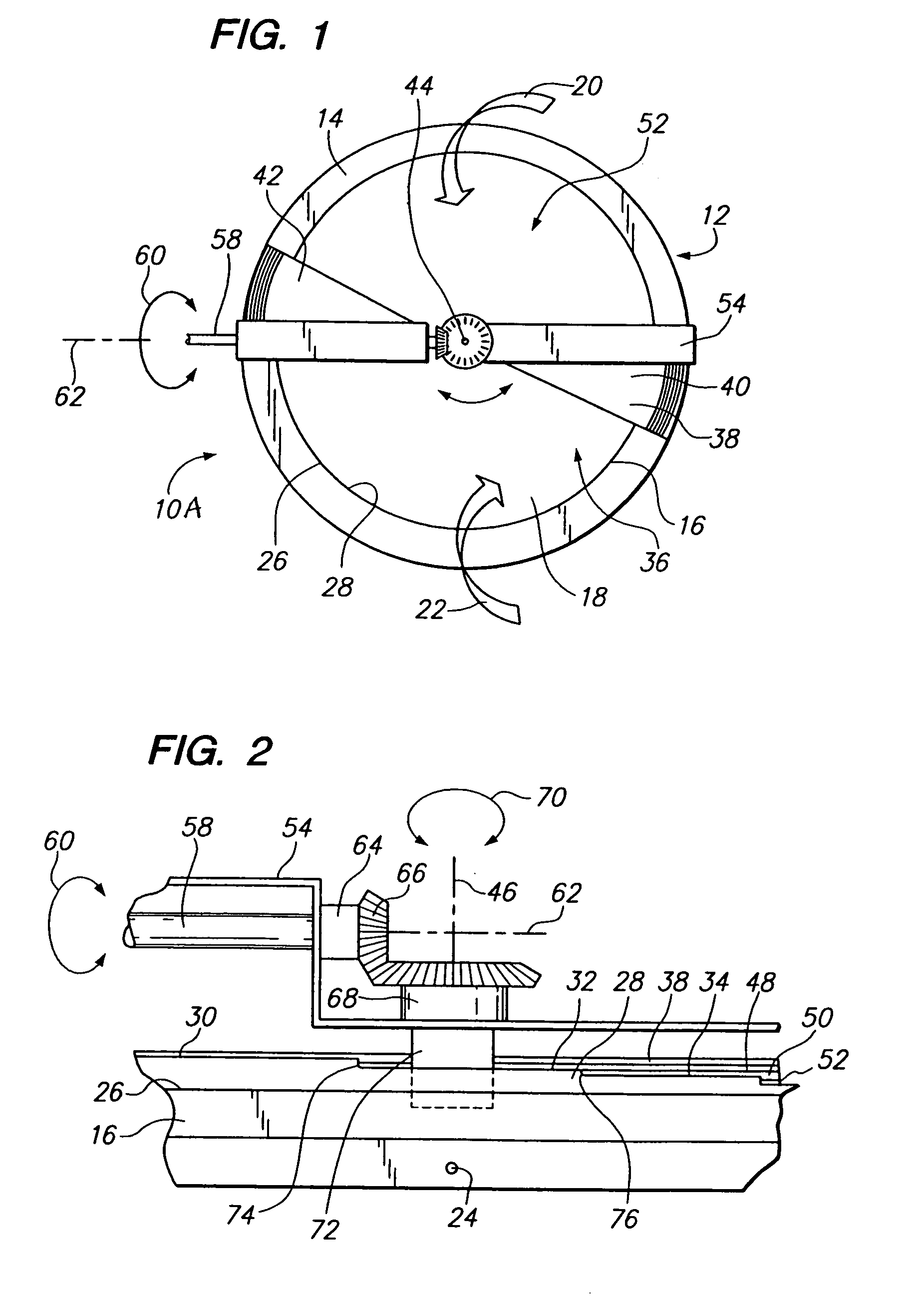
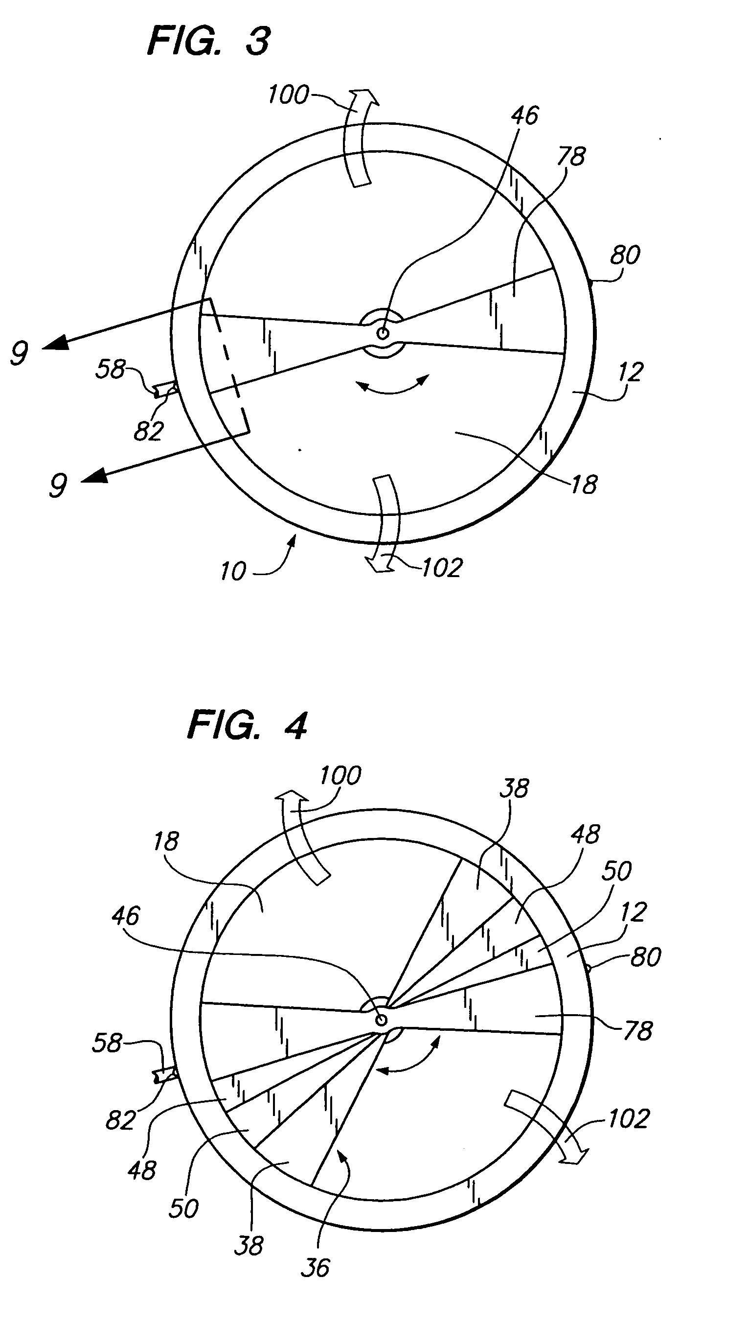
[0044]Preferred embodiments of the present invention are shown in the drawings by reference character 10 followed by an upper case letter to denote distinct embodiment. Damper 10A includes as one of its elements a frame 12. Frame 12 possesses a base 14 and includes a wall portion 16 which extends outwardly therefrom. Frame 12 forms an aperture or opening 18 through the same which is generally used to direct the passage of fluids such as air, directional arrows 20 and 22, FIG. 1. Frame 12 may be constructed of metallic material, although other materials such as composites plastics, and the like would suffice in this regard. Frame 12 is mounted within a ventilation system adjacent a filter or within a duct by conventional means such as fasteners, clamps, and the like. O...


PUM


Abstract

A damper utilizing a frame having a base and a wall portion extending outwardly from the same. The wall portion supports a stepped edge which is positioned to at least partially circumvent and aperture formed by the frame. A plurality of flanges are positioned in overlying relationship and slidably move relative to one another by a mechanical mechanism. A plurality of flanges ride on a stepped edge portion to cause fanning of the flanges across the aperture to selectively occlude the aperture or a portion thereof.

Description

CROSS-REFERENCE TO RELATED APPLICATIONS[0001]The present application is a Continuation-in-Part of my prior filed application; Ser. No. 10 / 153,287 filed 21 May 2002, now U.S. Pat. No. 6,712,335.BACKGROUND OF THE INVENTION[0002]The present invention relates to a novel and useful fluid damper.[0003]Dampers are used to control fluid such as air in edifices and other facilities. Airflow control is acutely necessary in clean structures, often requiring dampers in the ceiling and floor.[0004]In the past, dampers have followed two basic designs a “butterfly” and a “split butterfly” arrangement. Both designs utilize a central axis in which blades are extended outwardly and lies perpendicular to the flow of air. Unfortunately, these prior designs suffer from deficiencies in that positioning of the blades or “set” is often lost due to the flow of air against the blades. Thus, the control of airflow via the prior art designs is difficult to achieve. In addition, noise is easily generated by the...

Claims


Application Information

Patent Timeline
Patent Type & Authority Patents(United States)
IPC IPC(8): F16K3/03F16K51/00
CPCF16K3/03
Inventor NAUGHTON, BART
Owner NAUGHTON BART
Learn More