
Armrest arrangement in automotive seat

a technology for automotive seats and armrests, which is applied in the direction of convertible stools, sofas, chairs, etc., can solve the problems of affecting the smooth operation of the armrest, affecting the quality of the armrest, and the damper mechanism is quite complicated, so as to prevent the unfavorable abrupt or quick rotation of the armrest, the effect of increasing the contact for

Inactive Publication Date: 2005-12-06
TACHI S CO LTD
View PDF8 Cites 5 Cited by
  • Summary
  • Abstract
  • Description
  • Claims
  • Application Information

AI Technical Summary

Benefits of technology

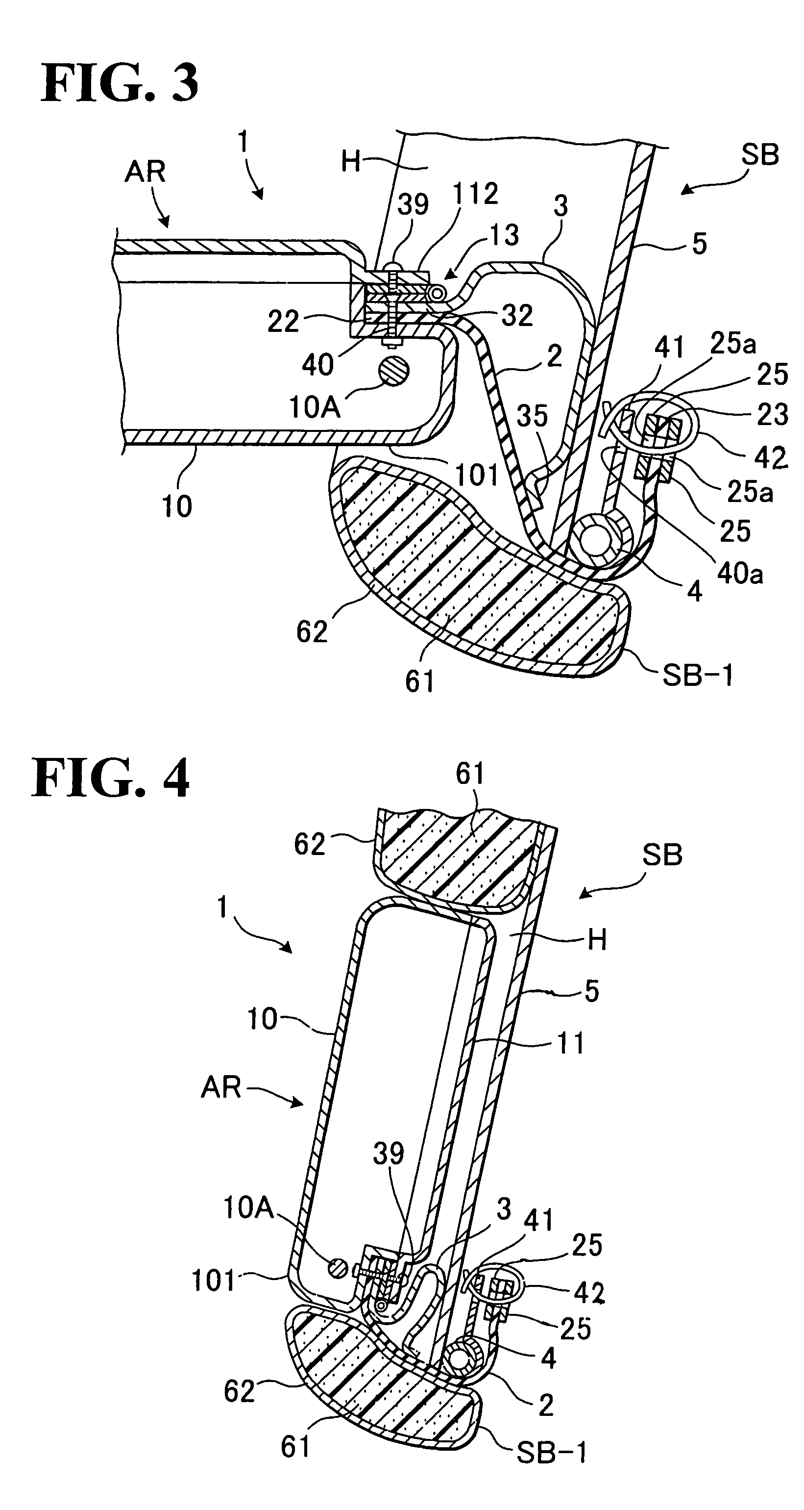
The present invention provides an improved armrest arrangement in a seat back of automotive seat that is simplified structurally and allows for easy rotation of the armrest with minimal force required on the user's side. The armrest arrangement includes a storage portion in the seat back, an armrest rotatably mounted in the storage portion, and an elastic means for resiliently biasing the armrest in a direction to the storage portion. The elastic means works to accelerate the rotation of the armrest when the user rotates it from the use position to the storage position, and to suppress an accelerated rotation of the armrest when the user draws and rotates it from the storage portion. The elastic means may comprise an elastic contractible / extendible element of a band shape. The invention also provides a means for covering and preventing the elastic means from being viewed from the storage portion when the armrest is located in the use position.

Problems solved by technology

However, the foregoing conventional armrest arrangement has been with the problem that, when a user draws the armrest from the storage portion, the armrest is abruptly rotated downwards to the use position with a slam, hence degrading the quality and operation of armrest.
In attempt to solve such problem, it has been proposed that the recessed storage portion be narrowed in width relative to the armrest to create a frictional force therebetween to moderate the downward rotation of the armrest, which however requires an undesired force on the user's side to draw the armrest and impairs a smooth operation of the armrest.
But, such damper mechanism is quite complicated in structure and therefore increases costs involved.

Method used


Image

  • Armrest arrangement in automotive seat
  • Armrest arrangement in automotive seat
  • Armrest arrangement in automotive seat

Examples


Embodiment Construction

[0019]Referring to FIGS. 1 to 4, there is illustrated one preferred mode of arrangement for rotatably securing an armrest in a seat back in accordance with the present invention, which is generally designated by (1).

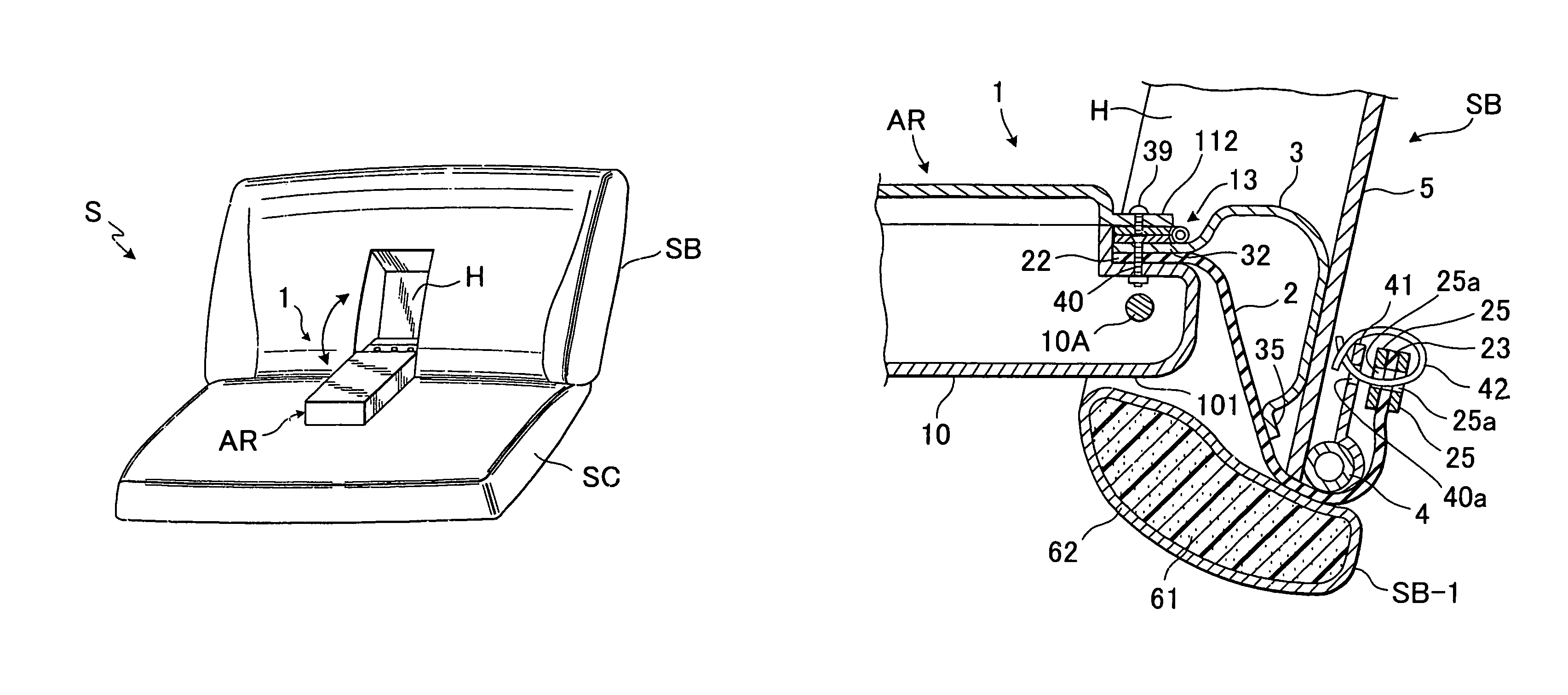
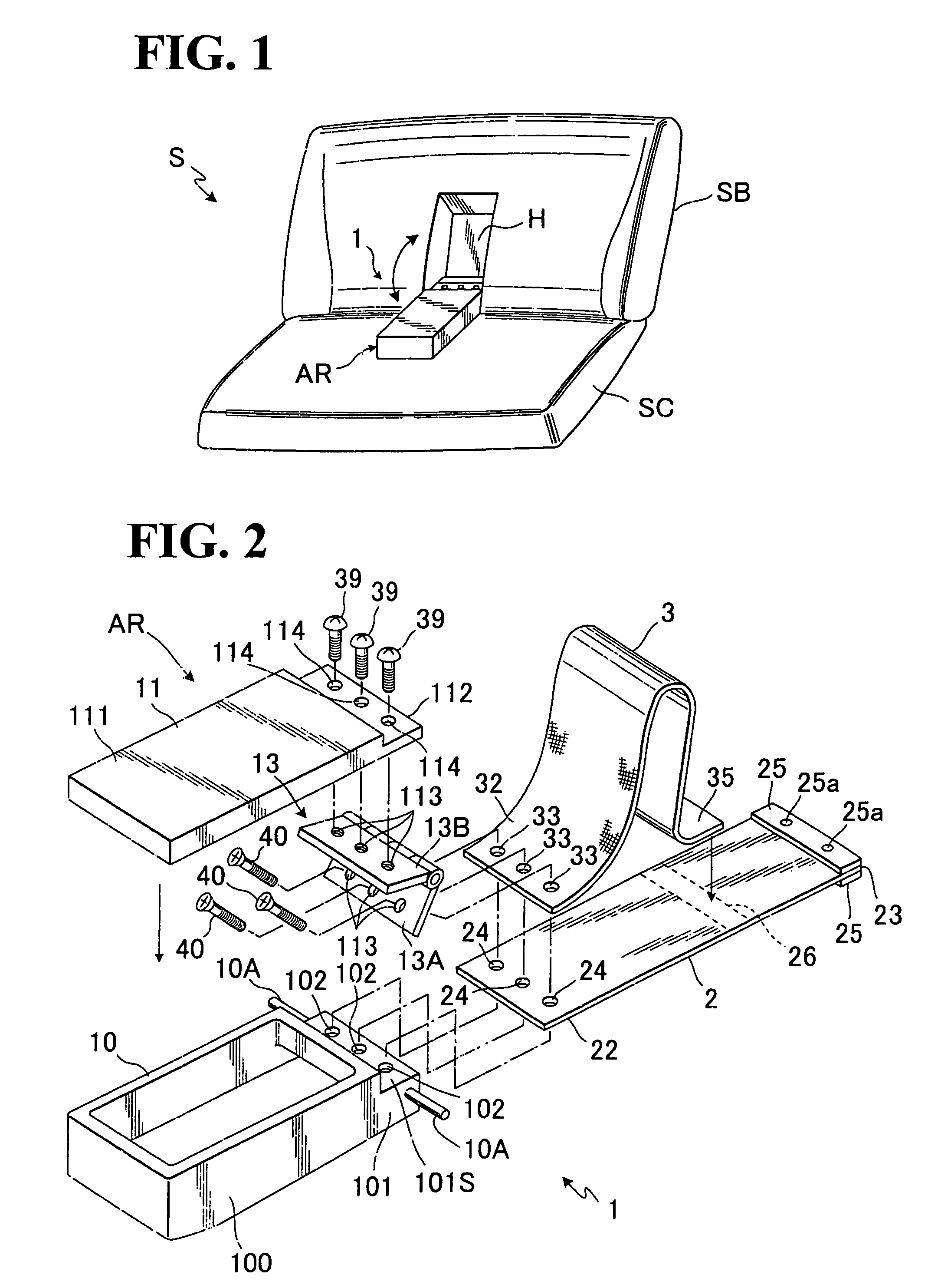
[0020]FIG. 1 shows a rear seat (S) of bench seat type for use in an automobile (not shown), which comprises a seat back (SB) and a seat cushion (SC). Designation (AR) denotes an armrest rotatably provided to the seat back (SB). The seat back (SB) is formed with a recessed storage portion (H) in which the armrest (AR) may be stored when in no use.

[0021]As shown in FIG. 2, the armrest (AR) itself comprises an upper cover portion (11) and a lower body portion (10). The upper cover portion (11) is formed by a main region (111) of a rectangular plate configuration and a securing flange region (112) defined in one end of the main regions (111), the securing flange region (112) having three threaded holes (114) (114) (114) formed therein. On the other hand, the lower body porti...


PUM


Abstract

An armrest arrangement in an automotive seat is provided to makes rotation of an armrest smooth and moderate. According thereto, an armrest is rotatably mounted in a storage portion formed in a seat back of the seat so as to be displaceable between a storage position at that storage portion and a use position, and an elastic band element is provided between the armrest and the seat back in order to resiliently bias the armrest in a direction to the storage portion. A covering element may be provided to cover such elastic band element to thereby prevent it from being viewed outwardly.

Description

BACKGROUND OF THE INVENTION[0001]1. Field of the Invention[0002]The present invention relates to an armrest in automotive seat. In particular, the invention is directed to an arrangement for rotatably securing the armrest in a seat back of an automotive rear seat.[0003]2. Description of Prior Art[0004]Various kinds of armrests are provided in automotive seats. In the case of armrest mounted in a seat back of an automotive rear seat, the hitherto normal arrangement of the armrest is such that a recessed storage portion is defined in the seat back of rear seat and the armrest itself is pivotally mounted in the recessed storage portion so as to be rotatable thereinto and away therefrom. According thereto, the armrest, when in no use, is normally stored in the recessed storage portion, and a user who wishes to use the armrest can easily draw and rotate the armrest from the recessed storage portion to a substantially horizontal use position.[0005]However, the foregoing conventional armre...

Claims


Application Information

Patent Timeline
Patent Type & Authority Patents(United States)
IPC IPC(8): B60N2/75
CPCB60N2/4613B60N2/4686B60N2/757B60N2/793
Inventor YUHKI, KAZUMASANANAI, HISASHINISHIYAMA, MAMI
Owner TACHI S CO LTD
Learn More