Vehicle brake system

a brake system and vehicle technology, applied in the direction of braking systems, pedestrian/occupant safety arrangements, tractors, etc., can solve the problems of difficult to avoid surrounding obstacles, difficult for the host vehicle to turn, and complex behavior of the host vehicle in a turning motion, so as to reduce the strain on the neck of the passenger, reduce the acceleration in the turning direction of the host vehicle, and improve the passenger protection

Inactive Publication Date: 2005-12-06
HONDA MOTOR CO LTD
View PDF8 Cites 11 Cited by
  • Summary
  • Abstract
  • Description
  • Claims
  • Application Information

AI Technical Summary

Benefits of technology

[0010]In accordance with a prediction signal transmitted from the collision predicting means, a detection signal transmitted from the collision direction detecting means and a detection signal transmitted from the colliding object speed detecting means, the brake controller controls the operation of the brake mechanism to allocate braking forces to the respective wheels so as to prevent the turning of the host vehicle in a collision. Even when a colliding object collides with the host vehicle from behind obliquely or from a rear off-center position, braking forces can be allocated in accordance with the collision type and the speed of the colliding object to restrain the turning motion of the host vehicle.
[0011]As a result, acceleration in the turning direction exerted on passengers in the host vehicle can be restrained, resulting in further improved passenger protection. For example, since the body of a passenger seated in a seat is prevented from swinging sideways, the neck of the passenger can be supported on a headrest of the seat, and strain on the neck of the passenger can be more reliably reduced.
[0012]Further, since the turning motion of the host vehicle is restrained, the behavior of the host vehicle in a collision can be stabilized, easily avoiding obstacles if any around the host vehicle.

Problems solved by technology

However, a vehicle behind as a colliding object often collides with a host vehicle traveling ahead obliquely from behind or from a rear off-center position relative to the host vehicle (offset collision).
In order to enhance the passenger protection, the acceleration in the turning direction exerted on passengers should be taken into account, which is not easy.
Further, the behavior of the host vehicle in a turning motion is intricate.
It is not easy for the host vehicle to avoid surrounding obstacles if any.

Method used


Image

  • Vehicle brake system
  • Vehicle brake system
  • Vehicle brake system

Examples


Embodiment Construction

[0028]The following description is merely exemplary in nature and is in no way intended to limit the invention, its application or uses.

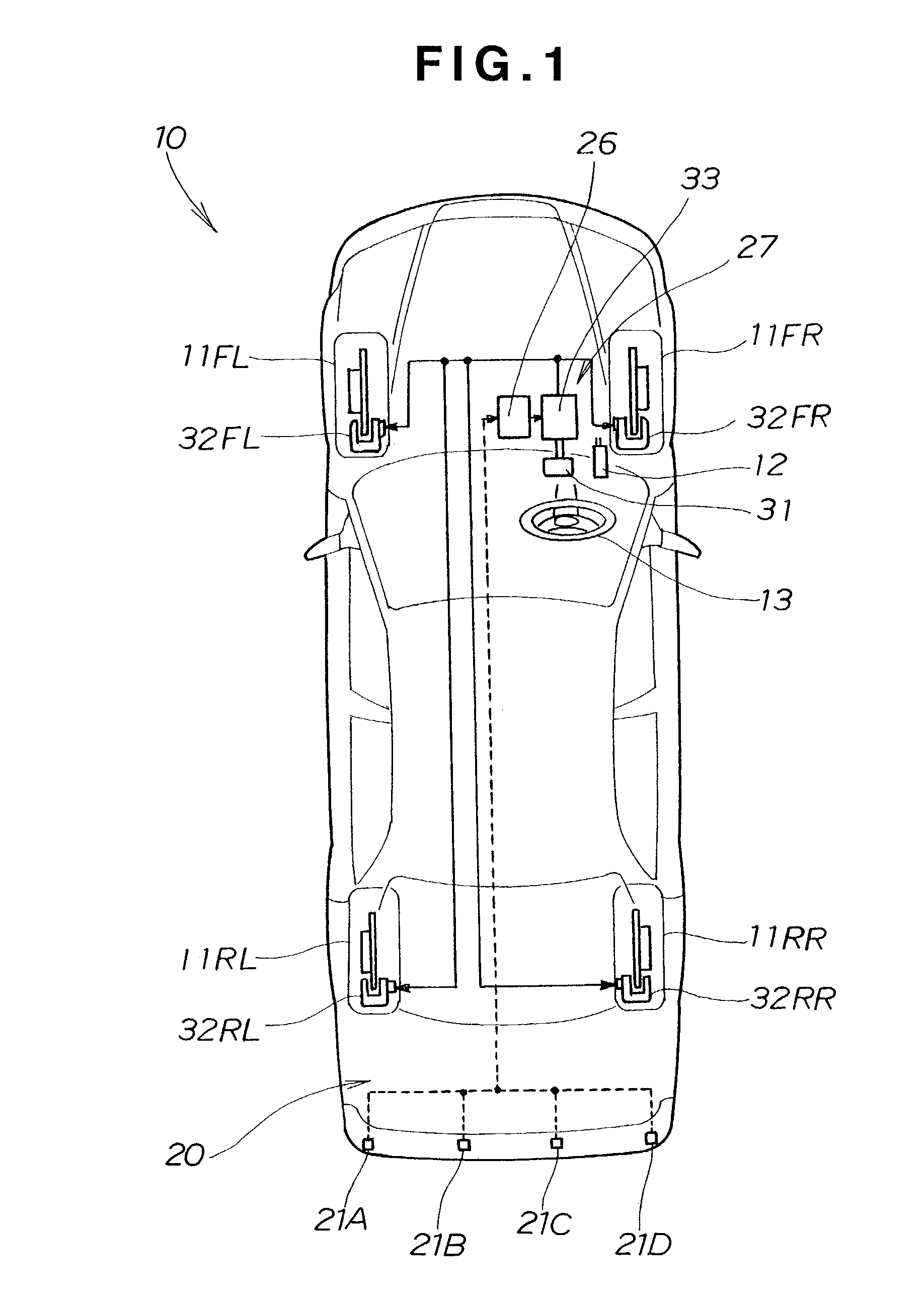
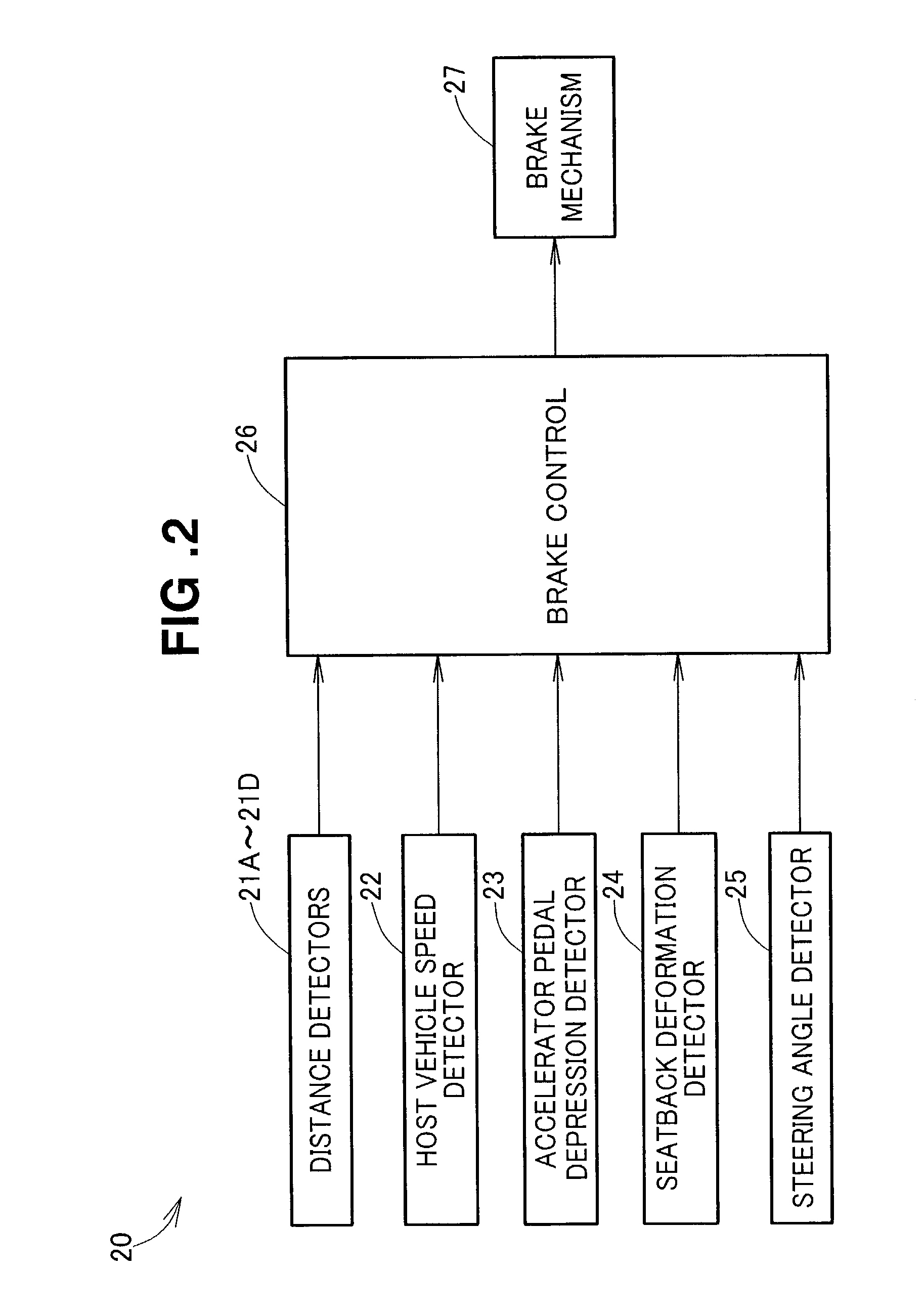
[0029]As shown in FIG. 1, a vehicle 10 is equipped with a vehicle brake system 20. The host vehicle 10 has a brake mechanism 27 for individually braking a left front wheel 11FL, a right front wheel 11FR, a left rear wheel 11RL and a right rear wheel 11RR, a brake controller 26 for controlling the operation of the brake mechanism 27, an accelerator pedal 12, a steering wheel 13, and a plurality of (e.g., four) distance detectors 21A to 21D.

[0030]The brake mechanism 27 is a hydraulic brake mechanism which can be operated by a brake pedal 31. The brake mechanism 27 has a left front brake 32FL for braking the left front wheel 11FL, a right front brake 32FR for braking the right front wheel 11FR, a left rear brake 32RL for braking the left rear wheel 11RL and a right rear brake 32RR for braking the right rear wheel 11RR, and a main brake 33 (such as a br...


PUM


Abstract

A vehicle brake system includes a brake mechanism for individually braking wheels, and a brake controller for controlling the brake mechanism against an oblique collision from behind or an offset collision with a host vehicle. The controller includes a collision predictor, a collision direction detector, and a colliding object speed detector. In accordance with a prediction signal transmitted from the collision predictor, a detection signal transmitted from the collision direction detector and a detection signal transmitted from the colliding object speed detector, the controller controls the operation of the brake mechanism to allocate braking forces to the respective wheels so as to prevent the turning of the host vehicle in a collision.

Description

TECHNICAL FIELD[0001]The present invention relates to a vehicle brake system for braking a host vehicle when anticipating a potential collision of a vehicle behind with the host vehicle.BACKGROUND ART[0002]Such a vehicle brake system is know from, for example, Japanese Patent Laid-Open Publication No. 2000-355273 entitled “VEHICLE PASSENGER PROTECTION SYSTEM”. This protection system will be briefly described with reference to FIG. 12 hereof.[0003]A conventional vehicle brake system 100 shown in FIG. 12 has a collision predicting means 101 for predicting an object which is likely to collide from behind with a host vehicle, a front obstacle detecting means 102 for detecting the presence of an obstacle in front of the host vehicle, a driving condition detecting means 103 for detecting the driving condition of the host vehicle, a brake operation detecting means 104 for detecting the operational state of brakes by a driver, a backseat occupant detecting means 105 for detecting the presen...

Claims


Application Information

Patent Timeline
Patent Type & Authority Patents(United States)
IPC IPC(8): B60R21/00B60R21/01B60R21/013B60R21/0132B60R21/0134B60T7/12B60T7/22B60T8/1755
CPCB60R21/013B60T7/22B60T8/17558B60R21/0132B60R21/0134B60R2021/01311B60T2201/024
Inventor YOSHIZAWA, RYOZONAKANISHI, ISAMU
Owner HONDA MOTOR CO LTD
Why Eureka
Try Eureka