

Hybrid transmission control system
a transmission control and hybrid technology, applied in the direction of engine-driven generators, process and machine control, propulsion mounting, etc., can solve the problems of preventing accurate driving force control, affecting durability, and being impossible to continue the revolution speed control
- Summary
- Abstract
- Description
- Claims
- Application Information
AI Technical Summary
Benefits of technology
Problems solved by technology
Method used
Image

Examples
Embodiment Construction
[0024]Referring to FIGS. 1 through 9, there are shown embodiments of a control system for a hybrid transmission in accordance with the present invention.
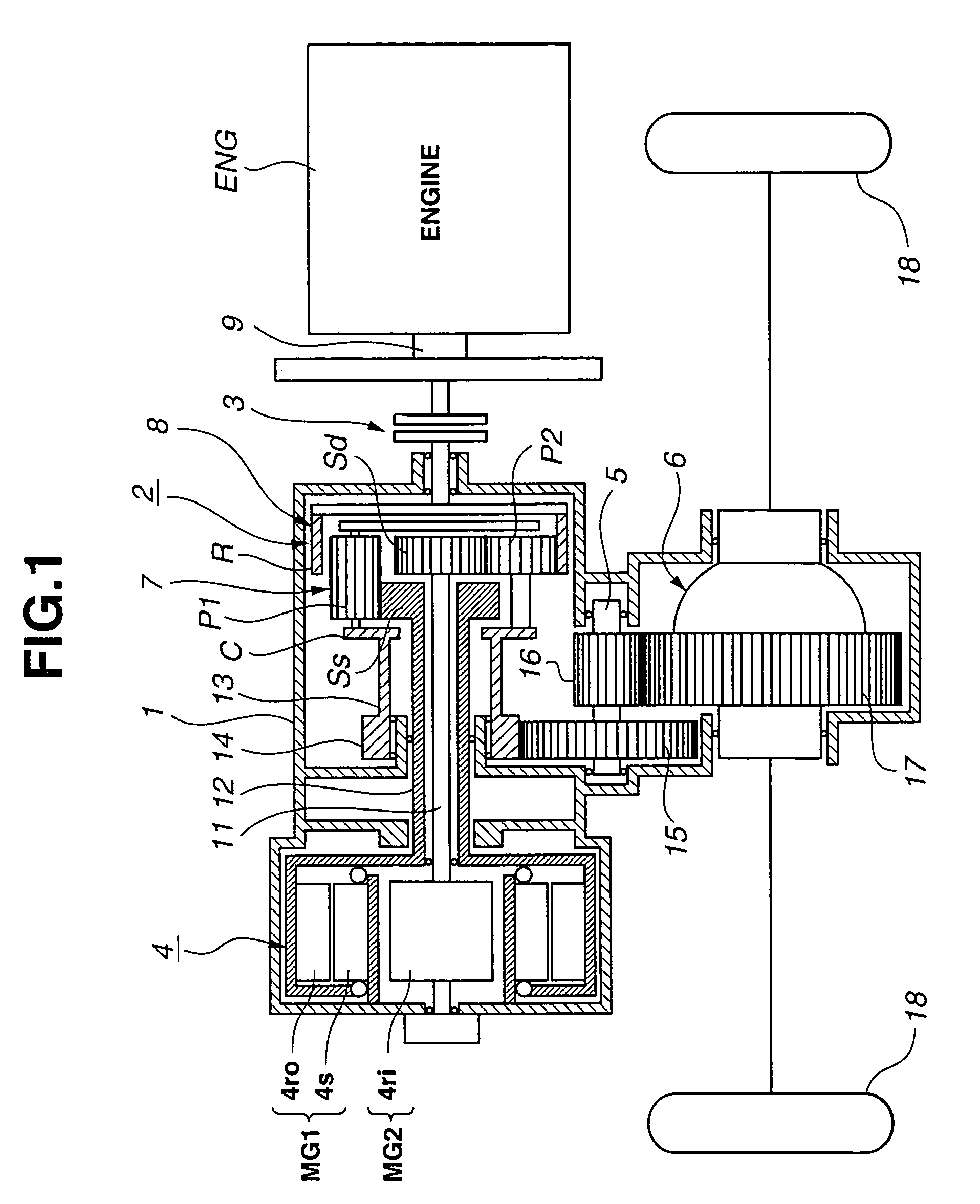
[0025]FIGS. 1 and 6 show a first embodiment of the control system for the hybrid (automatic) transmission in accordance with the present invention. In this first embodiment, the hybrid transmission is adapted to a transaxle of a front-wheel-drive vehicle. As shown in FIG. 1, the hybrid transmission comprises a transmission case 1, a Ravigneaux planetary gearset 2, and a compound-current double-layer motor 4 constructing first and second motor / generators MG1 and MG2. Ravigneaux planetary gearset 2 is built in transmission case 1 so as to be located at a left-hand side of an internal combustion engine (prime mover) ENG along an axial direction of transmission case 1 in FIG. 1. Further, compound-current double-layer motor 4 is built in a transmission case 1 so as to be located at the left-hand side of Ravigneaux planetary gearset 2 alo...
PUM
 Abstract
Description
Claims
Application Information