
Composite structure aircraft with tiltable rotors

A composite structure and tilt rotor technology, applied in the field of aircraft, can solve the problems of short endurance, poor flexibility, limited use, etc., and achieve the effect of improving the control system and high reliability

Pending Publication Date: 2021-02-05
FUZHOU UNIVERSITY
View PDF0 Cites 0 Cited by
  • Summary
  • Abstract
  • Description
  • Claims
  • Application Information

AI Technical Summary

Problems solved by technology

However, their applications are always limited by flexibility, payload and endurance, which are related to their own typical structure and power system
For example, although the rotorcraft has the ability of short take-off and landing, its battery life is relatively short.
Although fixed-wing unmanned aerial vehicles have a long endurance time, their use is limited by the flight site and their flexibility is poor

Method used


Image

  • Composite structure aircraft with tiltable rotors
  • Composite structure aircraft with tiltable rotors
  • Composite structure aircraft with tiltable rotors

Examples


Embodiment 1

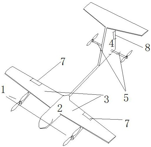
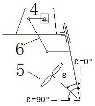
[0194] In this example, only a pair of tiltable rotors are used to meet the thrust requirements, which means less mechanism, lower cost, lower power consumption and longer flight time. as attached figure 1 As shown, propulsion system rotors 3 and 4 can be tilted from a vertical position (ε=0°) to a horizontal position (ε=90°) or vice versa by means of a four-bar linkage. When the aircraft enters the fixed-wing aircraft mode, rotors 1 and 2 stop working; meanwhile, rotors 3 and 4 provide power for the aircraft. The invention adopts a rotor smaller than that of common aircraft to meet the requirement of low thrust-to-weight ratio during cruising flight, thereby reducing the weight of the aircraft and improving cruising efficiency.

Embodiment 2

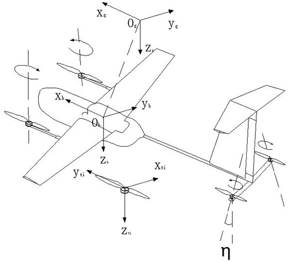
[0196] In aircraft modeling work, this example attaches the Body Fixed Frame (BFF) to the aircraft's Center of Gravity (CoG). Denote the inertial fixed frame (EFF) as O g x g the y g z g , whose origin is set at the start point. Unlike other similar works, we establish four auxiliary frames (AFs) in the coordinate system O i x ti the y ti z ti (i=1, 2, 3, 4) considering the inclination angle and roll angle, z ti axis along the propeller axis. x ti axis parallel to the longitudinal plane of the drone and perpendicular to z ti axis and perpendicular to the paper face outward. the y ti The axes are determined by the right-hand rule. The reference coordinate system is attached figure 2 shown. According to the principle of coordinate transformation, the transformation matrix between coordinate systems is given:

[0197]

[0198] φ, θ, ψ represent the Euler angles, c and s are the symbols of the cosine and sine functions respectively, η is the fixed roll angle us...

Embodiment 3

[0232] In this example, when designing the controller, the following methods are used:

[0233] ①Control distribution strategy based on channel throttling and trim calculation

[0234] For the composite structure aircraft with tiltable rotor described in the present invention, a control distribution method based on channel throttling and trim calculation is proposed. First, the relationship between the virtual control inputs of the four channels and the actual throttling of the propeller is established as follows:

[0235]

[0236] where δ Hi ,δ θi ,δ φi ,δ ψi (i=1,2,3,4) are the vertical channels δ H , pitch channel δ θ , Tumbling channel δ φ , yaw channel δ ψ The weight of the throttle valve.

[0237] When the aircraft is in equilibrium, that is Based on the nonlinear dynamic equation (11), the following disturbance balance equation is easily obtained:

[0238]

[0239] where Δ(·)=(·)-(·) op , "op" means the operation point.

[0240] According to the abov...


PUM


Abstract

The invention provides a composite structure aircraft with tiltable rotors. A fuselage of the aircraft comprises a main wing and an empennage which are used for cruising in the air, the main wings arearranged at the middle section of the fuselage; the empennage is arranged at the tail part of the fuselage; the aircraft is further provided with a rotor wing used for providing power for the aircraft. The rotor wings comprise a first rotor wing group arranged at the fixed wing and a second rotor wing group arranged at the rear part of the fuselage; when the aircraft takes off or lands, the orientations of the rotors in the first rotor set and the second rotor set are vertical so as to provide lift force for the fuselage, and when the aircraft is in an air cruise state, the orientations of the rotors in the second rotor set are adjusted to the horizontal direction so as to provide thrust for the aircraft. According to the invention, the advantages of the fixed-wing aircraft and the rotoraircraft are well integrated, and the existing control system is improved, so that the control system has higher reliability, interference resistance and control performance.

Description

technical field [0001] The invention relates to the technical field of aircraft, in particular to an aircraft with a composite structure capable of tilting rotors. Background technique [0002] Fixed-wing unmanned aerial vehicles and rotary-wing unmanned aerial vehicles, as representatives of traditional unmanned aerial vehicle structures, have played an important role in military and civilian fields for a long time. However, their application is always limited by flexibility, payload and endurance, which are related to their own typical structure and power system. For example, although the rotorcraft has the ability of short take-off and landing, its battery life is relatively short. Although fixed-wing unmanned aerial vehicles have a long endurance time, their use is limited by the flight site and their flexibility is poor. Contents of the invention [0003] The invention proposes a composite structure aircraft with a tiltable rotor, which better combines the advantage...

Claims


Application Information

Patent Timeline
IPC IPC(8): B64C27/22B64C27/32B64C27/52G06F30/15G06F17/16G06F17/13G06F119/14G05D1/10G05D1/08G05D1/04G05B11/42
CPCG05D1/101G05D1/0808G05D1/042B64C27/22B64C27/32B64C27/52G06F30/15G06F17/16G06F17/13G05B11/42G06F2119/14
Inventor 雷瑶王家鼎冯志成
Owner FUZHOU UNIVERSITY
Learn More