Portable sign system

a sign system and portability technology, applied in the field of sign systems, can solve the problems of increased time and effort in the process, misalignment of the sign, and ineffective methods of rotational fixation, etc., and achieve the effect of promoting smoothness and reducing friction

Inactive Publication Date: 2005-12-06
DAKTRONICS
View PDF5 Cites 30 Cited by
  • Summary
  • Abstract
  • Description
  • Claims
  • Application Information

AI Technical Summary

Benefits of technology

[0011]Still another significant aspect and feature of the present invention is a portable sign system incorporating a worm gear for automatic locking of a digital display panel and attached solar array to prevent inadvertent rotation of the digital display panel and solar array.
[0013]An additional significant aspect and feature of the present invention is a portable sign system incorporating a wide base upper assembly to provide for stability of the digital display panel and solar array during raising and during rotation of the digital display panel and solar array.
[0014]A still additional significant aspect and feature of the present invention is a portable sign system having a wide base upper assembly including a UHMW plastic stabilizing disk for stabilization and for use to reduce friction and to promote smoothness during rotation.

Problems solved by technology

Such methods require one or more additional steps to lock and fix the sign in the required direction, thus requiring additional time and effort spent in the process.
Such methods of rotational fixation can be rendered moot or ineffective if the operator of the portable sign fails for whatever reason to lock the sign in the desired viewing position whereby wind forces could cause the sign to rotatingly migrate or weather vane from the desired viewable position.
Additionally, unwanted rotation, such as if the sign is unlocked, could occur if the trailer upon which the sign was mounted was not perfectly level, whereby the sign can be misaligned such as by gravitational forces.
Rotation and elevating of a sign can also be hampered while operating under adverse wind conditions to cause elevational or rotational binding or resistance.

Method used


Image

  • Portable sign system
  • Portable sign system
  • Portable sign system

Examples


Embodiment Construction

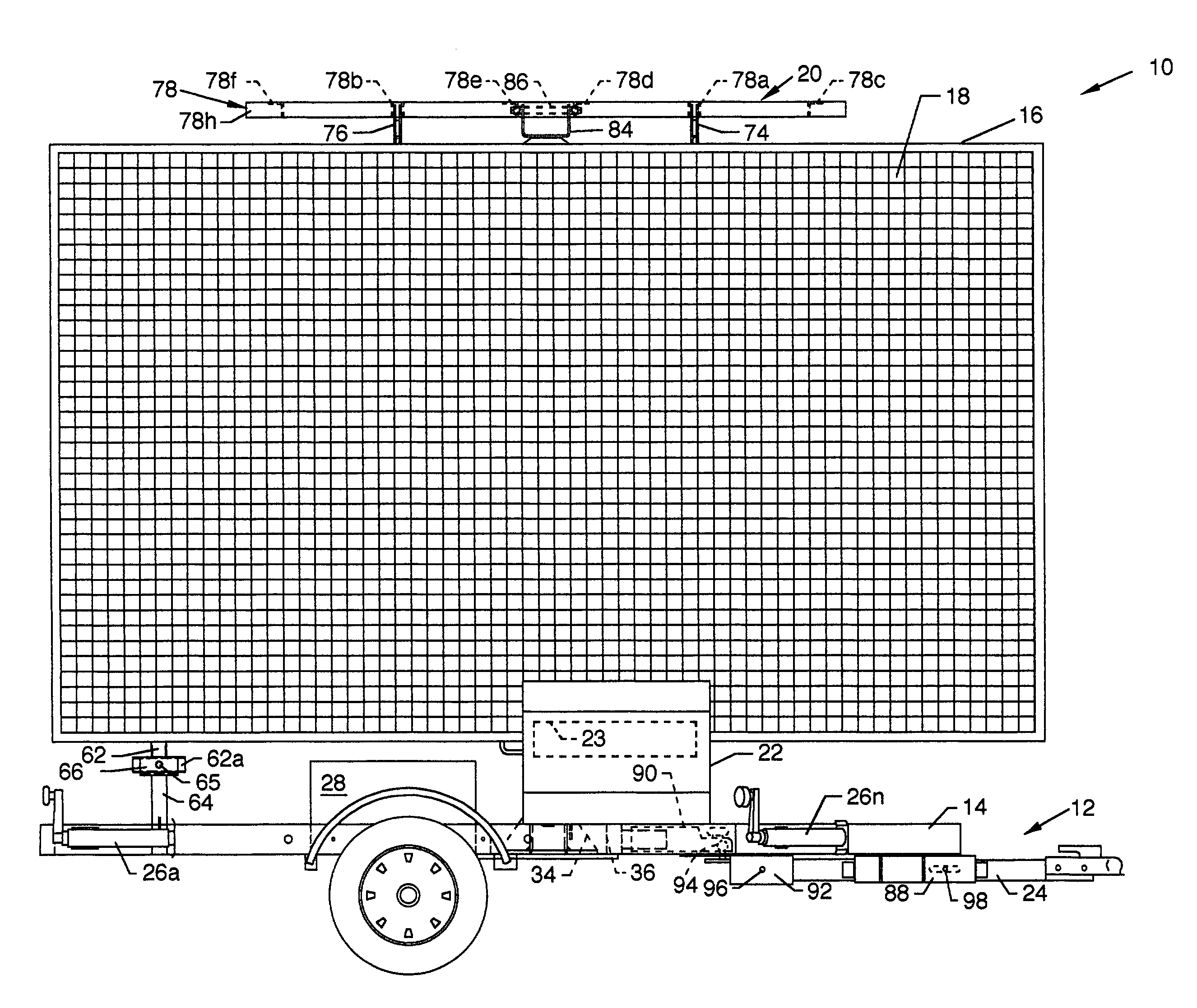
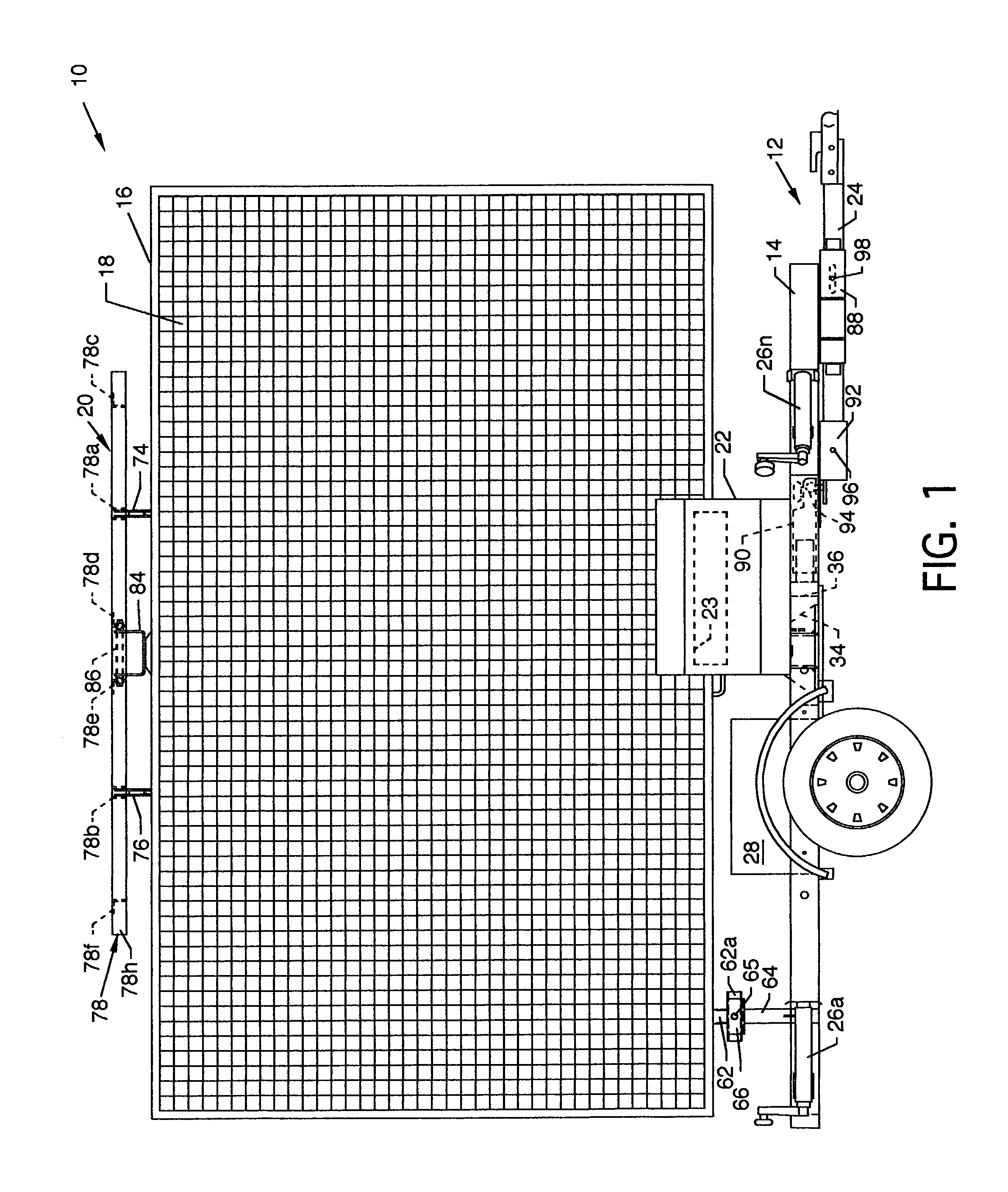
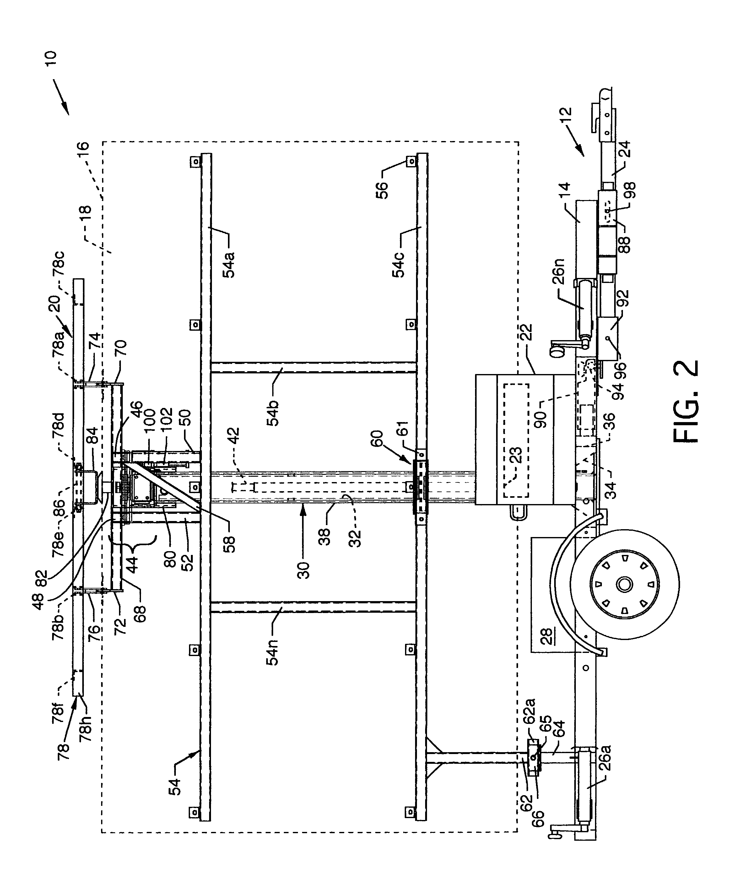
[0029]FIG. 1 illustrates a plan view of a portable sign system 10, the present invention. Readily discernible and visible components of the invention include a trailer 12, a trailer frame 14, a digital display panel 18 having a surrounding peripheral digital display frame 16 rotatably secured to the trailer frame 14, as later described in detail with reference to FIG. 2, a solar array 20, a control panel 22, a detachable tow bar 24, a plurality of jacks 26a–26n secured to the trailer frame 14, and a platform 28 transversely mounted to the trailer frame 14. The control panel 22 is utilized to control the functions of the portable sign system 10 and includes controls to operate the mechanical functions including a microprocessor 23 to control the messages displayed on the digital display panel 18. The microprocessor 23 is also incorporated to provide for azimuthal control of the digital display panel 18 automatically or by remote control. An electrical manual switch 164, shown in FIG....


PUM


Abstract

A portable sign system being self-contained and having a digital display panel which can be hydraulically raised to a suitable height and subsequently be rotated by a worm gear which is manually driven or electrically driven by a motor. A broad based upper assembly having an UHMW plastic stabilizing plate and rotation plates and attached worm gear drive serves as a rotatable and stabile mount for a digital or other display panel and an attached solar array. The digital display panel is automatically locked in azimuthal position by the worm gear drive without a conscious operator effort. Azimuth orientation of the digital display panel can be effected by a hand crank, manually by an electrical switch, automatically by an onboard computer control or by remote control.

Description

CROSS REFERENCES TO RELATED APPLICATIONS[0001]None.BACKGROUND OF THE INVENTION[0002]1. Field of the Invention[0003]The present invention is for a sign system, and more particularly is for a portable sign system.[0004]2. Description of the Prior Art[0005]Prior art portable signs often require that a sign be elevatable for unrestricted viewability and that the sign be rotatable to orient the sign to a viewer's field of vision for the best suitable viewing. After the sign or display is rotated, it is desirable to lockingly fix the sign in a desirable azimuthal position. Such locking may be accomplished by various methods of frictional engagement by personnel of various qualifications. Such methods require one or more additional steps to lock and fix the sign in the required direction, thus requiring additional time and effort spent in the process. Such methods of rotational fixation can be rendered moot or ineffective if the operator of the portable sign fails for whatever reason to lo...

Claims


Application Information

Patent Timeline
Patent Type & Authority Patents(United States)
IPC IPC(8): G08B5/00G08B5/36G09F9/30G09F13/00G09F21/04
CPCG09F21/04G09F9/3026
Inventor MORGAN, JAMES B.WIEMANN, BRADLEY T.LEGUALT, JEAN-LOUISLEGAULT, JACQUESPEETROONS, ALEXJACOB, LUC
Owner DAKTRONICS
Why Eureka
Try Eureka