Method and apparatus for dynamically matching impedance

a dynamic matching and impedance technology, applied in the field of communication systems, can solve the problems of limited transmission range, limited bit error rate (ber) associated with the system, and the characteristics of real-world transmission systems, which rarely perfectly coincide with theoretical calculations, so as to facilitate dynamic impedance matching and reduce or eliminate at least some shortcomings

Inactive Publication Date: 2005-12-06
SAGEMCOM BROADBAND
View PDF4 Cites 23 Cited by
  • Summary
  • Abstract
  • Description
  • Claims
  • Application Information

AI Technical Summary

Benefits of technology

[0006]The present invention recognizes a need for a method and apparatus operable to facilitate dynamic impedance matching in a communication network. In accordance with the present inve

Problems solved by technology

Failure to match impedance can result in various undesirable consequences, such as crosstalk, in-band and out-of-band interferences, limitations on transmission range, and limitations on bit error rates (BER) associated with the system.
Real world transmissions systems' characteristics, however, rarely perfectly coincide with theoretical calculations, and often change over time.
For example, bridge taps, discontinuities in wire gauge, discontinuities in the overall line, lengths of wire installed but unused or forgotten, and mismatched terminations can all create mismatches between a theoretical impedance match and actual impedance values.
This approach suffers for sev

Method used


Image

  • Method and apparatus for dynamically matching impedance
  • Method and apparatus for dynamically matching impedance
  • Method and apparatus for dynamically matching impedance

Examples


Embodiment Construction

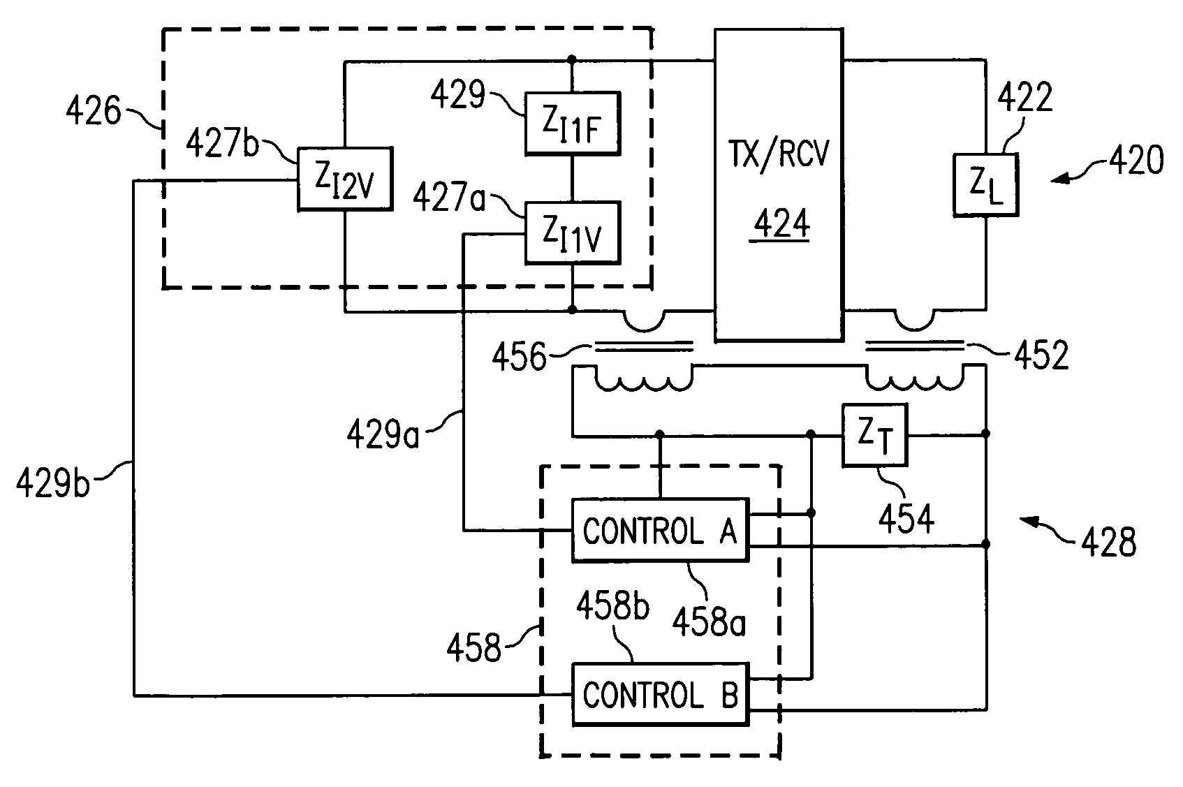
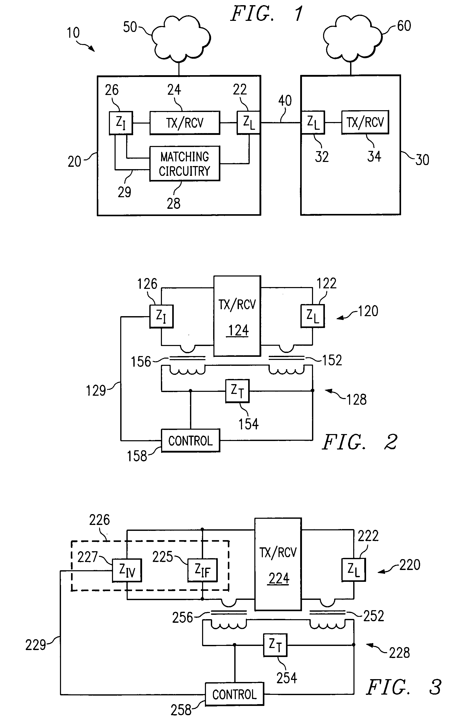
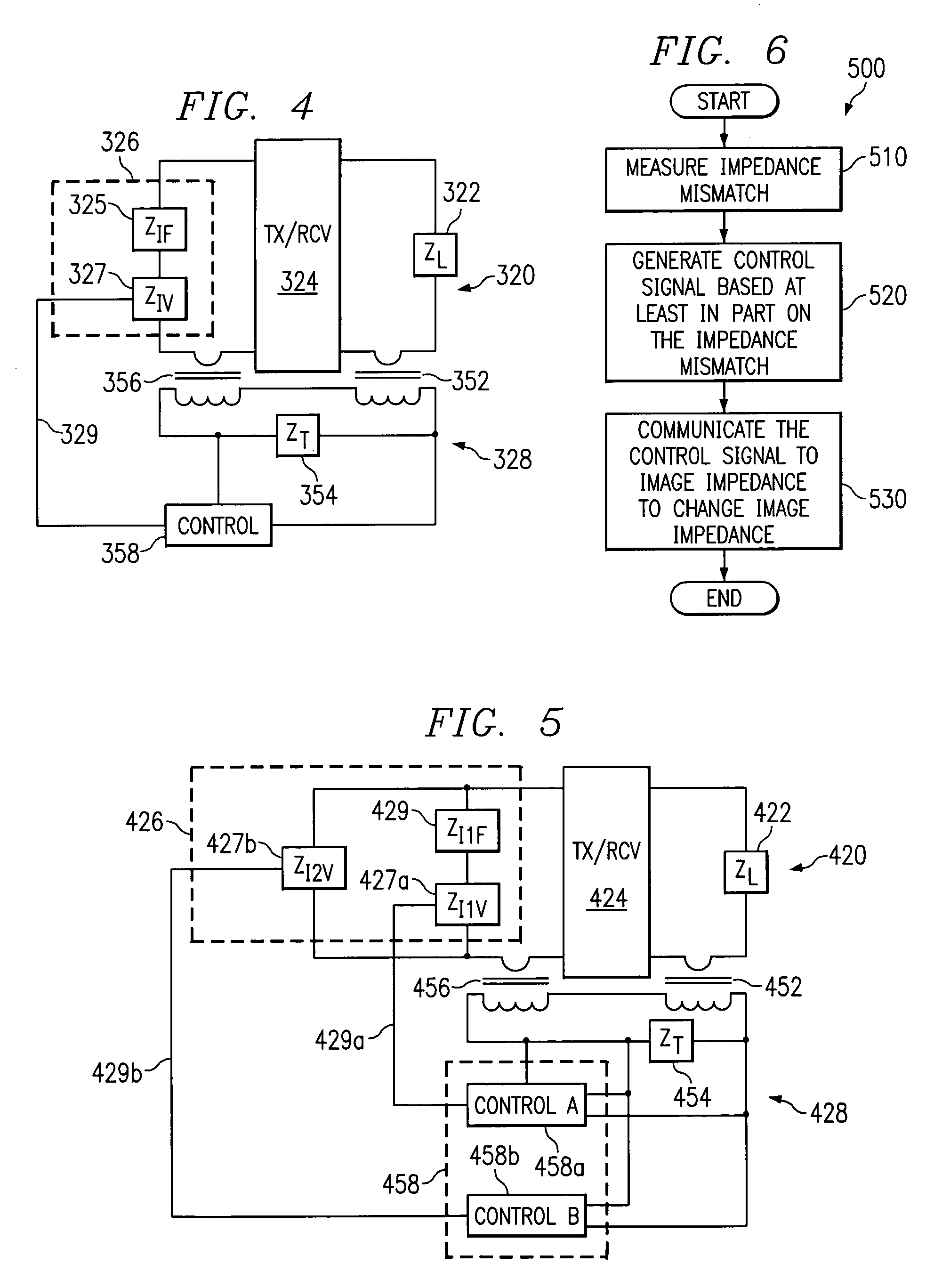
[0019]FIG. 1 is a block diagram of an exemplary embodiment of a system 10 implementing a technique for dynamic impedance matching. System 10 includes a first network element 20 coupled to a second network element 30 by a communication link 40. Throughout this disclosure, the term “coupled” denotes direct or indirect communication between two or more items said to be “coupled.” Items described as being “coupled” may or may not be physically connected to one another, and may or may not have other devices or elements residing between them.

[0020]Network elements 20 and 30 could comprise any hardware, firmware, software, or combination thereof operable to communicate with one another over one or more communication links 40. Network elements 20 and 30 could also communicate with other network elements over communication links or networks 50 and 60. In addition, communication devices besides network elements 20 and 30 may share communication link 40.

[0021]As one particular non-limiting exa...


PUM


Abstract

In one aspect of the invention a communication device including circuitry operable to facilitate dynamic impedance matching includes an image impedance operable to be coupled to a receiver/transmitter pair associated with a line impedance. The device also includes matching circuitry coupled to the line impedance and the image impedance, the matching circuitry operable to measure an impedance mismatch between the line impedance and the image impedance and to generate a control signal based on the measured impedance mismatch. The image impedance is operable to be varied to more closely match the line impedance based at least in part on the control signal.

Description

TECHNICAL FIELD OF THE INVENTION[0001]The present invention relates to the field of communication systems, and more particularly to a system and method operable to facilitate dynamic impedance matching.BACKGROUND OF THE INVENTION[0002]Network elements communicating information over physical media typically see a line impedance, a source termination impedance, and a receiver impedance. To maximize system performance, these impedances should be matched with an image impedance, typically at the network element. Failure to match impedance can result in various undesirable consequences, such as crosstalk, in-band and out-of-band interferences, limitations on transmission range, and limitations on bit error rates (BER) associated with the system.[0003]One approach to matching impedances has been to implement a static image impedance at the network element, whose value has been selected as a best guess impedance match for all situations. Real world transmissions systems' characteristics, h...

Claims


Application Information

Patent Timeline
IPC IPC(8): H03H7/40H04L25/02H04M7/04
CPCH03H7/40H04L25/0278
Inventor GARCIA, JOHN D.
Owner SAGEMCOM BROADBAND
Why Eureka
Try Eureka