Apparatus and method for controlling polarization of an optical signal

Inactive Publication Date: 2005-02-15
CHEETAH OMNI
View PDF44 Cites 23 Cited by
  • Summary
  • Abstract
  • Description
  • Claims
  • Application Information

AI Technical Summary

Benefits of technology

The present invention recognizes a need for a method and apparatus operable to economically facilitate control of an optical signal's state of polarization. In accordance with the present inve

Problems solved by technology

Signals polarized parallel to the two principal axes experience differential delay, which—coupled with the random variation in polarization modes—leads to pulse broadening, intersymbol interference, and bit error ratio (BER) impairment.
Many communication systems consider unacceptable any pulse broadening greater than ten percent of the bit period.
As a result, it has been estimated that polarization mode dispersion renders over twenty percent of all currently deployed fiber unsuitable for transmission at ten Giga-bits per second, and over 75% of all installed fiber unsuitable for transmission at forty Giga-bits per second.
This approach, however, is too slow to be effective for most applications.
Another approach is to mechanically squeeze the fiber at strategic locations and times. This techni

Method used


Image

  • Apparatus and method for controlling polarization of an optical signal
  • Apparatus and method for controlling polarization of an optical signal
  • Apparatus and method for controlling polarization of an optical signal

Examples


Example

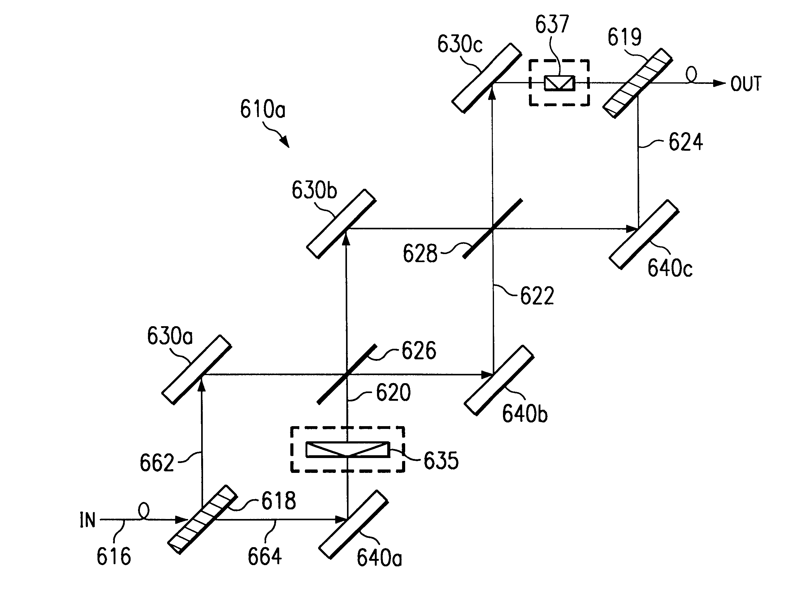
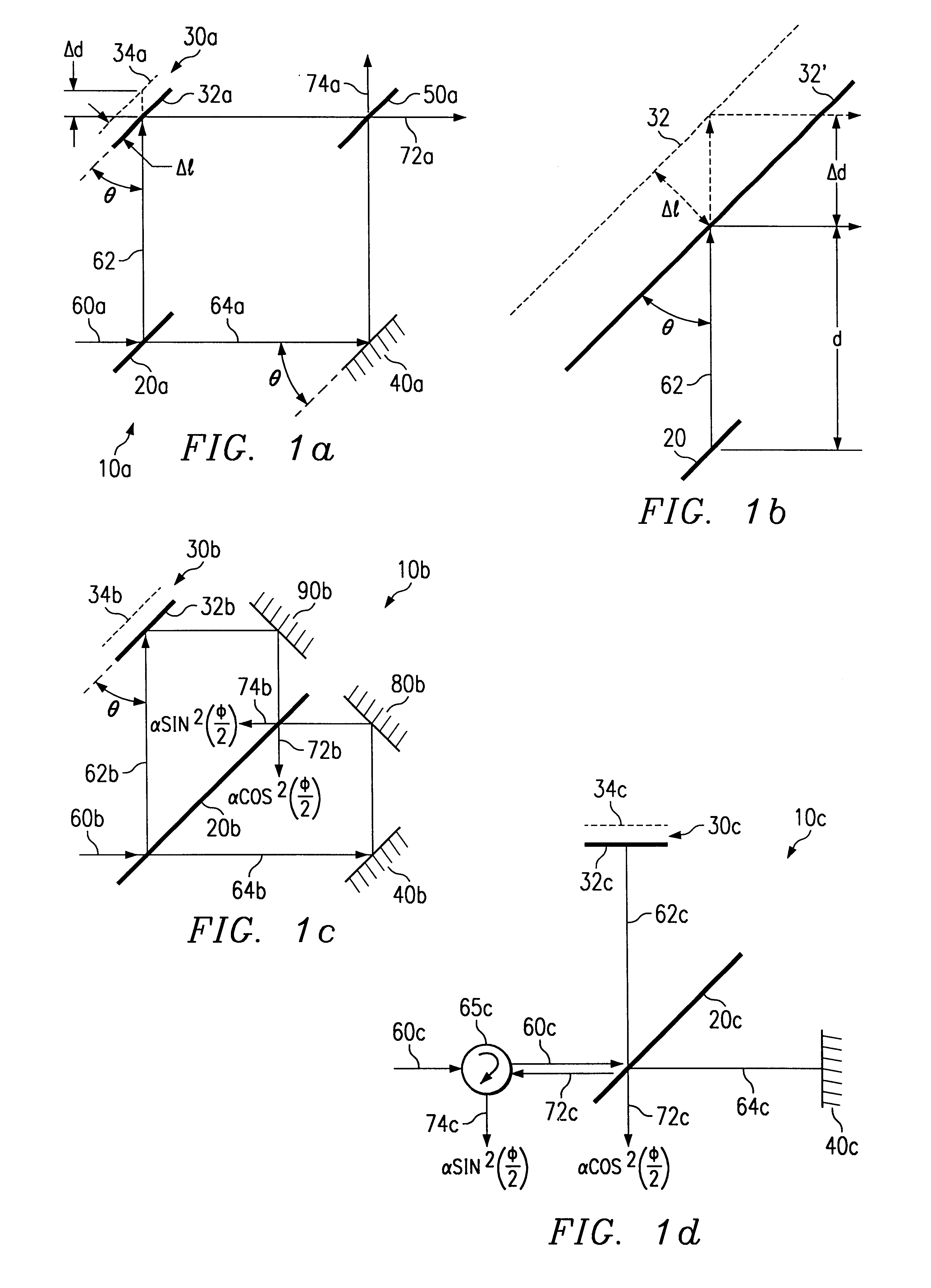
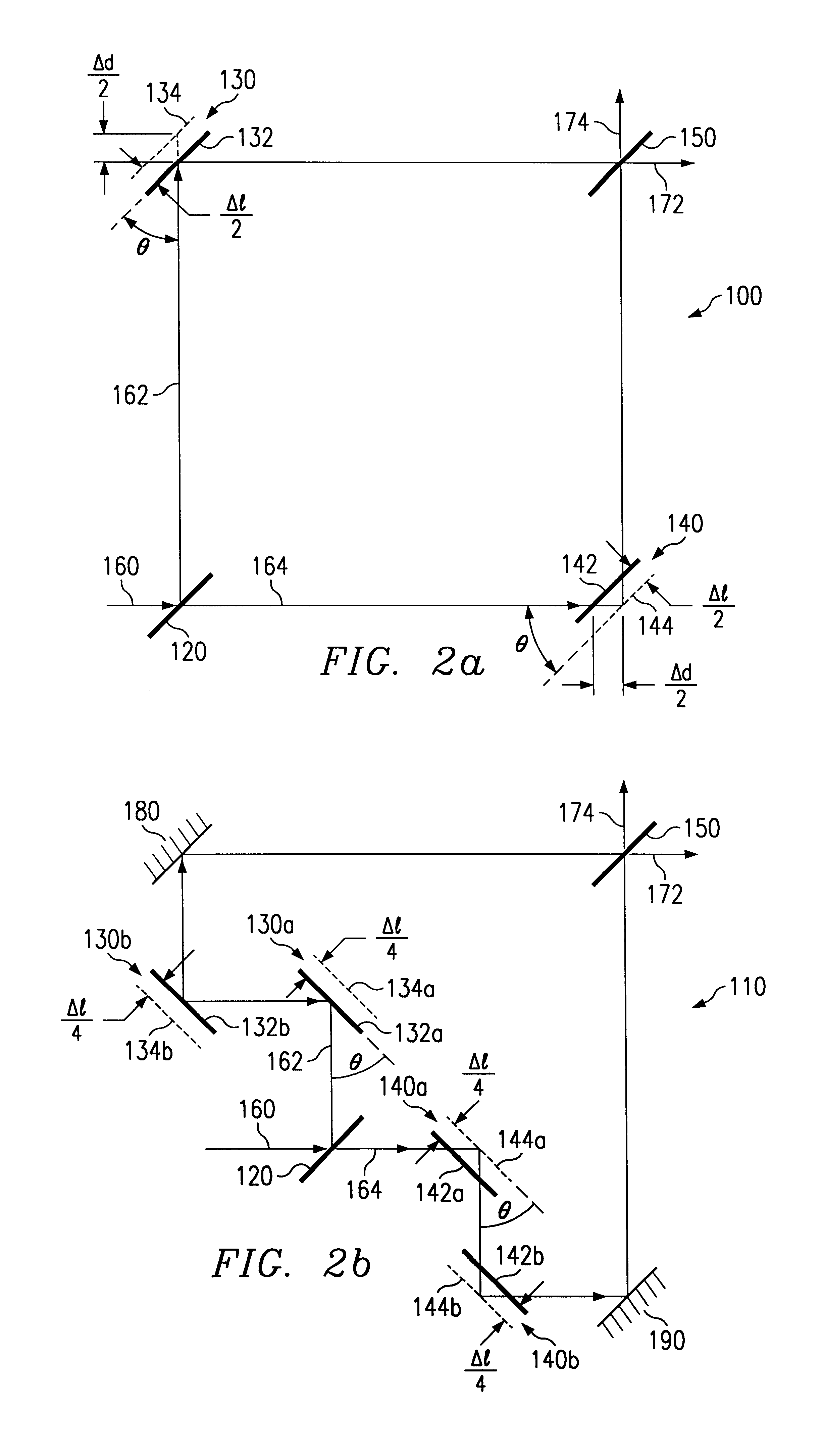
I. Building Blocks for High Speed Optical Signal Processing

FIG. 1a is a block diagram of one exemplary embodiment of an apparatus 10a operable to provide high speed optical signal processing. Throughout this document, the term “signal processing” includes attenuation, switching, phase shifting, polarization control, mitigation of polarization mode dispersion, or any other manipulation of one or more optical signals.

Apparatus 10a includes a beam splitter 20a, which communicates with mirrors 30a and 40a. Beam splitter 20a may comprise any structure or combination of structures operable to pass a first copy of an optical signal in one direction and a second copy of the optical signal in another direction. For example, in a particular embodiment, beam splitter 20a may comprise a partially silvered mirror. As another example, beam splitter 20a may comprise a mirror having one or more layers of a dielectric coating. As still another example, beam splitter 20a may comprise a fiber coupler....


PUM


Abstract

In one aspect of the invention, a polarization controller includes a first polarization beam splitter operable to receive an input optical signal having an input state of polarization and to separate the signal into a first and a second principal mode of polarization. The polarization controller further includes at least three stages of phase shifters each operable to introduce a phase shift between the first and second principal modes, at least one phase shifter comprising a beam splitter that is shared with at least one other of the phase shifters. The at least three stages of phase shifters include a first stage coupled to the first polarization beam splitter and a last stage coupled to a second polarization beam splitter. The second polarization beam splitter is operable to receive phase shifted copies of the first and second principal modes, and to align the phase shifted copies of the principal modes to an output state of polarization.

Description

TECHNICAL FIELD OF THE INVENTIONThe present invention relates to the field of communication systems, and more particularly to an apparatus and method operable to facilitate control of the state of polarization of one or more optical signals.BACKGROUND OF THE INVENTIONAs optical systems continue to increase the volume and speed of information communicated, polarization controllers are becoming increasingly important optical networking elements. For example, polarization controllers are essential in polarization multiplexed lightwave transmission systems. These systems can operate in a number of ways. In one embodiment, alternate bits can be polarized orthogonal to one another and combined to create a faster overall transmission rate. In another embodiment, densely packed adjacent wavelengths can be orthogonally polarized to minimize interaction between the adjacent wavelengths. In either case, a polarization controller is used to appropriately align the signals, states of polarizatio...

Claims


Application Information

Patent Timeline
IPC IPC(8): G02B26/06G02B26/00G02B26/08G02B27/28G01C19/72G02B6/34
CPCG02B6/272G02B6/2773G02B26/06G02B26/0808G02B26/0833G02B26/0841G02B27/283G02B27/286G02B26/0825Y10S359/90
Inventor ISLAM, MOHAMMED N.KUDITCHER, AMOS
Owner CHEETAH OMNI
Why Eureka
Try Eureka