Automated hair isolation and processing system

a processing system and hair technology, applied in the field of hair care industry, can solve the problems of hair appearing unnaturally the same color all, opaque colorants that are functionally equivalent to opaque printing inks and cannot be applied to all hairs on the head at once, and achieve the effect of narrowing the hair holding channels in places

Inactive Publication Date: 2005-12-13
KING CHRISTOPHER R
View PDF11 Cites 98 Cited by
  • Summary
  • Abstract
  • Description
  • Claims
  • Application Information

AI Technical Summary

Benefits of technology

[0014]Hair isolation also makes possible application of coloring agents to groups of one or a very few hairs at a time. This is desirable for, at least, two reasons. First, natural hair color is made up of slightly different colored hair strands. Conventional color-application attempts, however, often make the hair appear unnaturally the same color all over. Thus, controlled application of colors to specific isolated hairs is a way of countering this. Second, application of colorants to individual hairs makes possible the use of types of colorants that couldn't be applied to all the hair at once. For example, opaque colorants functionally equivalent to opaque printing inks couldn't be applied to all of the hairs on the head at once. This is because the adhesive binder that is necessary to hold the opaque pigments is so sticky that it would stick many hairs together if applied to them a consolidated group. However, such pigments might be feasibly applied to very limited numbers of hairs in isolation. Additionally, isolated application of other coatings used for hair-care can be applied is the manner, such as hair permanent curling and waving solutions, hair relaxers, and hair conventional hair ...

Problems solved by technology

Automated isolation of one or a very few scalp hairs as a group opens up many hair beautification opportunities that simply are not feasible otherwise.
Conventional color-application attempts, however, often make the hair appear unnaturally the s...

Method used


Image

  • Automated hair isolation and processing system
  • Automated hair isolation and processing system
  • Automated hair isolation and processing system

Examples


first embodiment

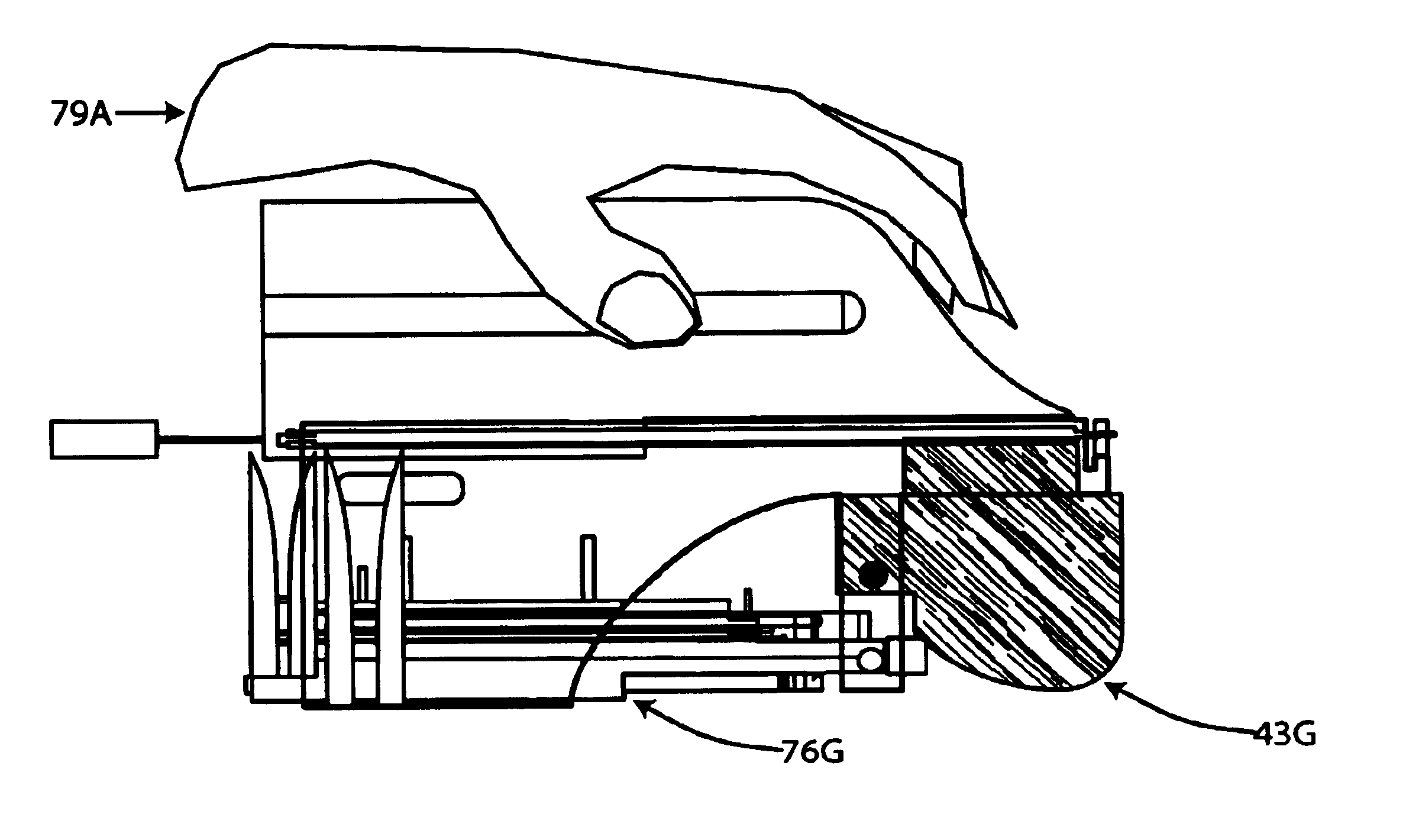
[0208]The most complex and challenging part of my invention to understand is this stack of about twenty layers. In general, I call this stack the processing circuit stack because it guides hairs through a planned path during the isolation and hair extension attachment processing. Depending on the context I may also call it similar names like the attachment circuit stack, the attachment stack, the attacher stack, the attacher, and the processing stack. In the case of the first embodiment, I will describe a system whose goal is hair extension attachment; I will call this stack the attachment circuit stack because it guides hairs through a planned path during the process of hair-extension attachment. For short, I may refer to it either as the attachment stack or attachment circuit.

[0209]To better understand the attachment circuit, I encourage you to think of a conventional electric hair trimmer as I describe it to you. Remember that the attachment circuit is very analogous to the movin...

second embodiment

[0744]This second embodiment of the sub-hair-diameter spaced pushback gate system uses a metering area composed of a series of attached compartments that become increasingly narrower, usually with increasing proximity to the attachment area. Referring to FIG. 116, this set of compartments 116A is usually formed by notches 116B in an entrance gate 116C that is imposed on an edge of a hair channel 116D. Each sub-compartment allows only hairs of an extremely specific diameter range in it. For example, a hair of an extremely thin diameter will not stop moving forward through the compartments until it reaches the entrance to a sub-compartment too thin for it, or the dead-end of the very thinnest sub-compartment. In a similar manner, a relatively wide diameter hair will stop much sooner in one of the wider compartments. If there are any thinner diameter hairs trailing a wider diameter hair, they will be stuck behind it and this is fine.

[0745]Once we have hairs of a specified diameter rang...


PUM


Abstract

A device comprised of hair-flow-channel guides continuously moved over the surface of the scalp. A track cap of parallel tracks is placed on the head to guide device's movement over the scalp along non-overlapping rows. At the front of the device is a hair-tensioning straightener that pulls hairs perpendicular to the scalp before and during processing. A bend-under assembly, formed by two pinching conveyer belts, facilitates hair exit from the channels by bending scalp-attached hairs beneath the walls of each hair channel. Intermittent intersection of each channel by an obstructing member isolates one or a few leading hairs for processing and forces trailing hairs to wait their turn for cosmetic processing behind it. Isolated scalp hairs may be cosmetically processed in ways including coloration; cross-section reshaping, hair-extension attachment and removal, and cutting to length according to position along track. Hair extensions removed at one position along a track cap are conveyed to corresponding holding clips and loaded in an order so as to permit their reattachment to the same scalp area. Hair extensions so held can be channeled and isolated for attachment, as are scalp hairs. A bend-under assembly can be used to draw one or a group of isolated hairs longitudinally through the chamber in which they are isolated facilitating cross-sectional reshaping of hairs or cutting to a preprogrammed length. Intersecting member and cosmetic processing actuation synchronized by computer.

Description

[0001]This application claims benefit of provisional application 60 / 063,574 filed Oct. 30, 1997.TECHNICAL FIELD[0002]The technical field of this invention is the hair-care industry, specifically, the industry responsible for beautification of hair on the human head.BACKGROUND ART[0003]This invention relates to an electromechanical system that can automatically isolate individual head hairs and mechanically process them in isolation so as to beautify them. For example, by attaching one or a very few hair extensions to one or a very few scalp hairs.[0004]It is well known that isolation of small numbers of skin-attached hairs is useful in the art of hair beautification. For example, highlighting requires the isolation of a small number of scalp hairs so that a coloring agent can be applied selectively to them, and many hair extension application techniques require the isolation of a small number of scalp hairs so that hair extensions can be attached to them. Likewise hair isolation is ...

Claims


Application Information

Patent Timeline
IPC IPC(8): A41G3/00A45D24/10A41G5/00A45C3/00A45D19/00A45D19/02A45D19/16A45D24/34B26B13/24B26B19/20B26B19/38
CPCA41G5/0086A45D19/02A45D24/34B26B19/20A45D19/16A45D2019/0091A45D2024/345B26B13/24B26B19/38A45D19/0066
Inventor KING, CHRISTOPHER R.
Owner KING CHRISTOPHER R
Why Eureka
Try Eureka