
Control valve with low noise and enhanced flow characteristics

a control valve and flow characteristics technology, applied in the field of control valves, can solve the problems of reducing fluid flow below the desired cv, hydrodynamic plug force and cavitation, and known solutions come at the price of additional expense in further trim requirements, so as to reduce the size of the required bonnet opening, improve noise characteristics, and reduce the effect of cos

Inactive Publication Date: 2005-12-13
FISHER CONTROLS INT LLC
View PDF30 Cites 24 Cited by
  • Summary
  • Abstract
  • Description
  • Claims
  • Application Information

AI Technical Summary

Benefits of technology

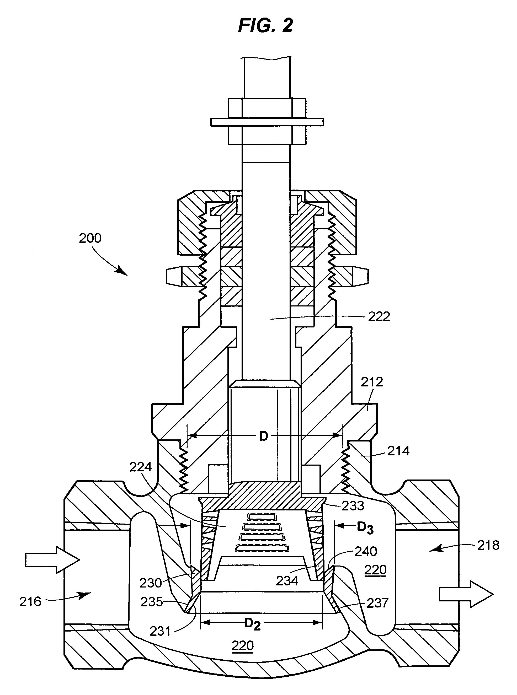
[0006]A control valve is disclosed which has improved noise characteristics and control characteristics over those normally associated with cage-free control valves. The control valve has noise-reducing and flow controlling components including one or both of a slotted cylindrical skirt and a tapered metal ring that provides a fluid-tight seal between the valve housing and the metal ring. The purpose of the metal ring is to provide a low cost alternative to a conventional screwed-in seat ring and to reduce the size of the required bonnet opening.
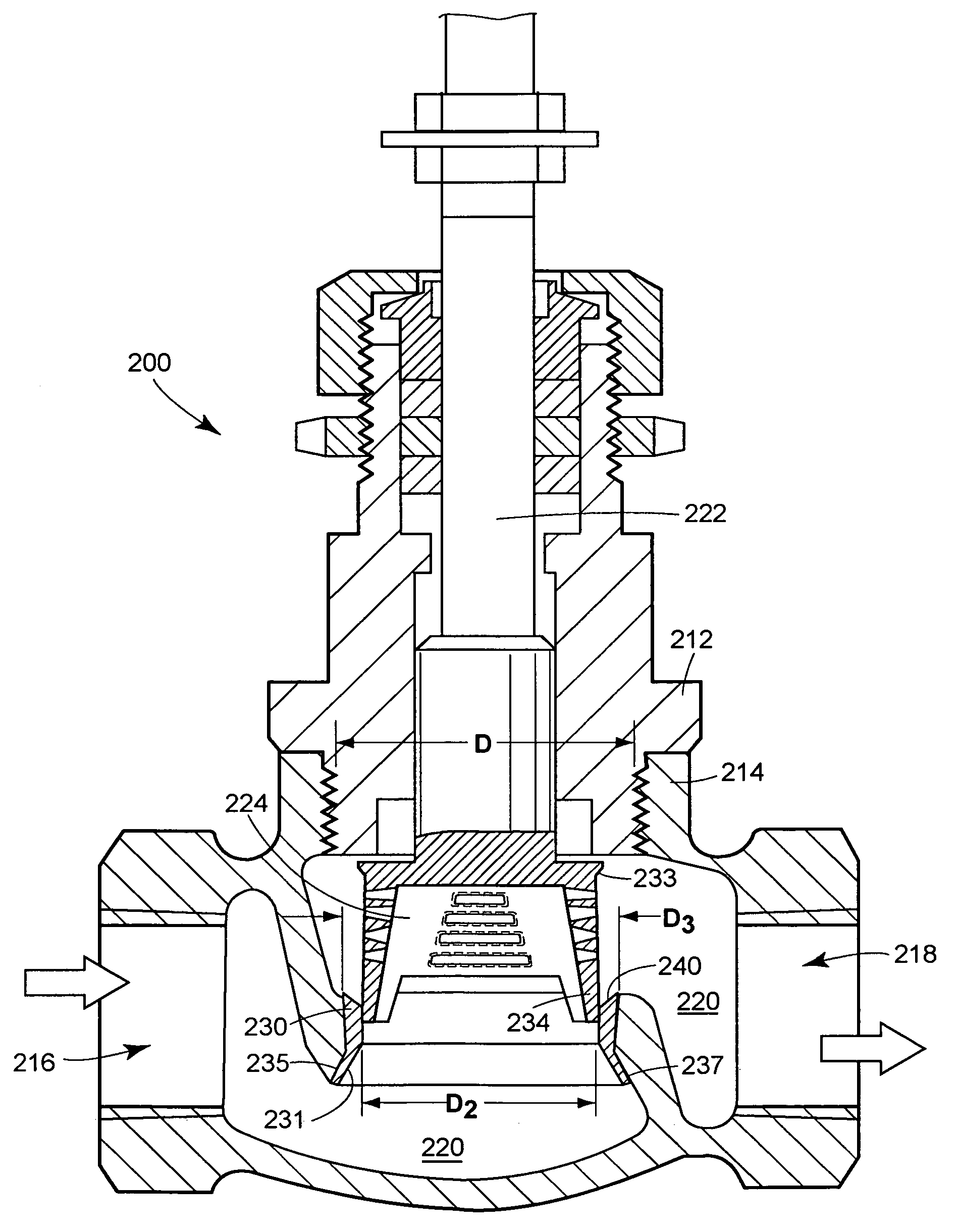
[0007]One embodiment is directed to a control valve including a housing defining a central orifice in fluid in communication with an inlet port and an outlet port, and a movable valve plug assembly having a skirt portion slidably engaged within the central orifice to control fluid flowing through the housing. The skirt portion defines a plurality of openings which can be slots to gradually control the flow of fluid through the housing while reducing cavitation. The lower terminating end of the control valve plug incorporates concave openings.
[0008]In one embodiment, the plurality of slots have lengths that progressively increase towards the lower terminating end, and each slot expands from the outside diameter of the cylindrical skirt portion at an angle of no less than 8 degrees and no more than 30 degrees. In an embodiment, plurality of slots are configured to be at varying distances from the lower terminating end of the cylindrical skirt along the circumference to prevent steps in the rate of flow through the control valve when the valve plug is being positioned.

Problems solved by technology

In a worst case, a skirt can produce vortices, turbulence and pressure gradients causing hydrodynamic plug forces and cavitations.
Thus, in a skirted valve, lowered pressure combined with skirt obstructions potentially reduces fluid flow below a desired Cv.
These known solutions come at the price of additional expense in further trim requirements, such as additional components and costly materials.

Method used


Image

  • Control valve with low noise and enhanced flow characteristics
  • Control valve with low noise and enhanced flow characteristics
  • Control valve with low noise and enhanced flow characteristics

Examples


Embodiment Construction

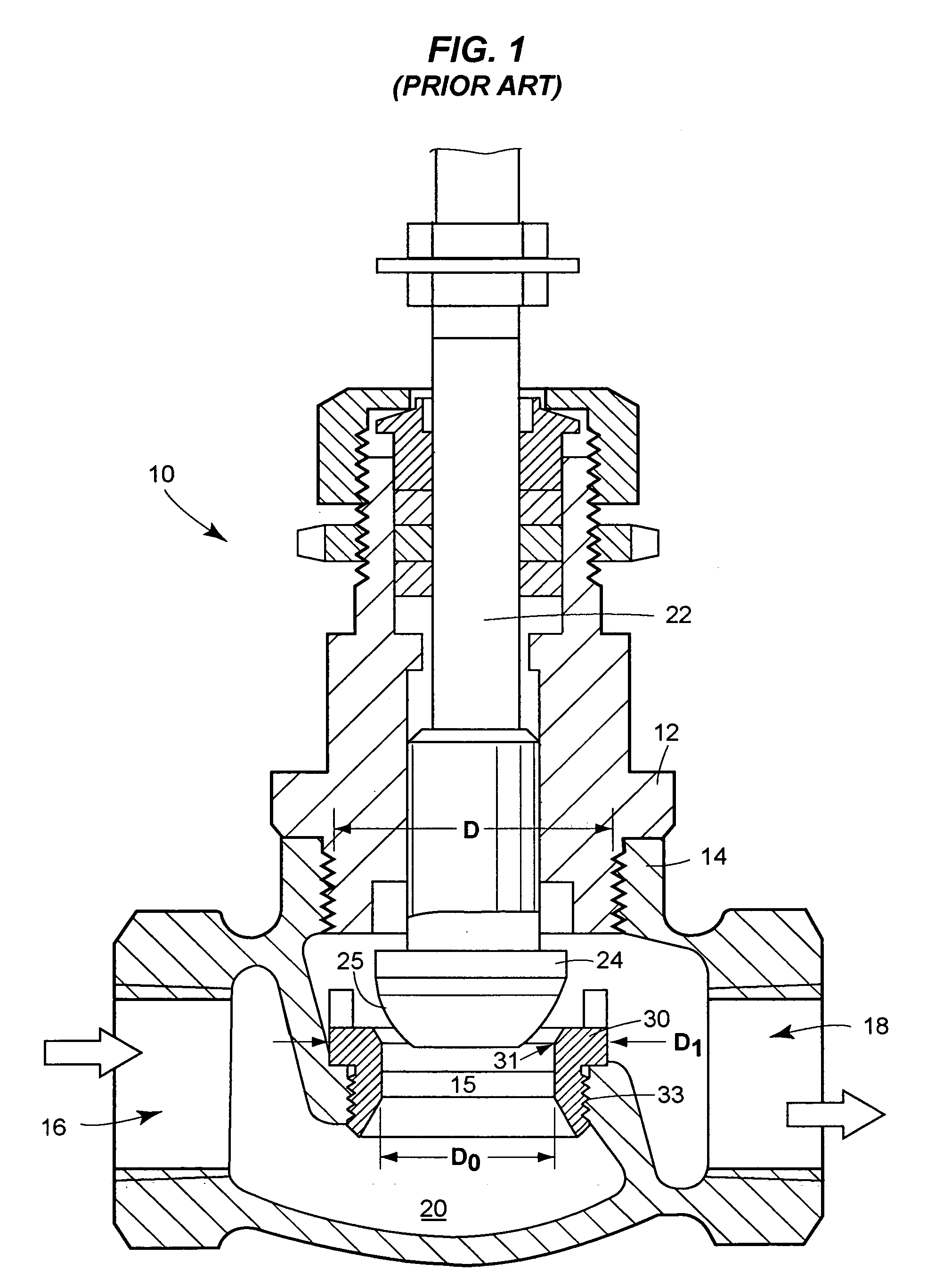
[0022]Referring to FIG. 1, a prior art control valve 10 is shown in a cross-sectional view. As shown, the control valve includes a bonnet 12, a valve housing 14 having a fluid inlet 16 and a fluid outlet 18. A connecting fluid passage 20 is defined by the interior walls of the housing 14 and is divided by a central orifice 15. The control valve further includes a plug stem 22 with attached plug 24. The plug stem 22 slidably engages central orifice 15, which is used to control fluid. Control valve 10 further includes an annular valve seat or seat ring 30, which provides a guiding and sealing surface 31 for engagement with valve plug 24 sealing surface 25. Seat ring 30 is shown as a conventional seat ring and includes a threaded surface 33 for screwably receiving control valve housing 14 as shown. Also shown in FIG. 1 are diameter measurements D1 and D0, which represent the inlet diameters through which fluids and gasses pass in the control valve 10. The size D0 is the central fluid p...


PUM


Abstract

A control valve that reduces noise and controls flow includes a slotted cylindrical skirt and / or a tapered metal ring. The metal ring has a tapered external surface for engaging a matching tapered bore within a valve housing. One embodiment is directed to a control valve including a housing defining a central orifice in fluid in communication with an inlet port and an outlet port, and a movable valve plug assembly having a skirt portion slidably engaged within the central orifice to control fluid flowing through the housing. The skirt portion defines a plurality of openings, which can be slots, to gradually control the flow of fluid through the housing while reducing cavitation. A method of controlling fluid flow in a process includes receiving fluids via an inlet port of a control valve, and controlling the flow of the fluid via a movable skirted valve plug with a plurality of tapered slots.

Description

RELATED APPLICATIONS[0001]This application is a Divisional of U.S. patent application Ser. No. 10 / 326,788 which was filed on Dec. 19, 2002 entitled “Control Valve with Low Noise and Enhanced Flow Characteristics.”FIELD OF THE INVENTION[0002]The present invention relates to control valves in general and, more specifically, to a control valve with a low-noise plug and enhanced flow characteristics suited for high pressure uses.BACKGROUND OF THE INVENTION[0003]There are many uses for high pressure control valves, including controlling flow of gas, steam, water and the like to compensate for load disturbances and regulate process variables within a control loop. Modern high-pressure control valves use low-noise trim to enable high pressure gases and liquids to flow without excessive noise and to maintain a desired flow coefficient (Cv). Valve plugs used to modulate the flow rate under high pressure and changing pressure conditions include globe valves that use either a seat ring trim or...

Claims


Application Information

Patent Timeline
Patent Type & Authority Patents(United States)
IPC IPC(8): F16K3/26F16K47/04
CPCF16K3/267F16K47/04Y10T137/86807Y10T137/86791
Inventor BAUMANN, HANS D.
Owner FISHER CONTROLS INT LLC
Learn More