Stapler device

a technology of stapler and stapler blade, which is applied in the direction of stapling tools, nailing tools, manufacturing tools, etc., can solve the problems of unsatisfactory staples or staple jams, unsatisfactory staples, and insufficient cartridge setting, so as to reduce the malfunction of the device, facilitate the installation and removal operation of cartridges, and facilitate the change operation.

Inactive Publication Date: 2005-12-13
ACCO BRANDS USA LLC +1
View PDF7 Cites 9 Cited by
  • Summary
  • Abstract
  • Description
  • Claims
  • Application Information

AI Technical Summary

Benefits of technology

[0005]This invention was made to solve the aforementioned problems, and an object thereof is to provide a cartridge that can be simply and easily installed, and properly urged toward the cartridge driver and retained in that state.
[0014]According to the staple device of this invention, when changing the cartridge, the cartridge can be retained and urged toward the staple driver in response to the installation of the cartridge. The problems that this process causes the operator are eliminated, and the cartridge can be properly and firmly set in the driver.
[0015]In addition, according to the staple device of this invention, the cartridge moves in a removal direction opposite that in which the cartridge was installed by moving the set lever that retains the cartridge to the release position, and thus the change operation is made extremely easy.
[0016]Moreover, according to the staple device of this invention, the cartridge installation and removal operation is simple, the cartridge can be properly set and retained in the staple driver, and malfunctioning of the device can be reduced.

Problems solved by technology

However, in these conventional devices, installing the cartridge involves a two step process of inserting the cartridge and then engaging it with the hook.
This process is a source of trouble because the cartridge is urged toward the driver and maintained in that state.
In addition, there are times when the cartridge is not set properly because the hook is manually engaged with the cartridge.
In this situation, the cartridge is not correctly positioned toward the staple driver, and in turn, there is a danger that this will cause unsatisfactory staples or a staple jam.
In particular, there is a problem in that in situations in which this staple device is incorporated into an image forming device or into a post-processing device of this image forming device, changing the cartridge is a heavy burden on the operator thereof because the staple device is positioned in a narrow location, thus making this process difficult.

Method used


Image

  • Stapler device
  • Stapler device
  • Stapler device

Examples


Embodiment Construction

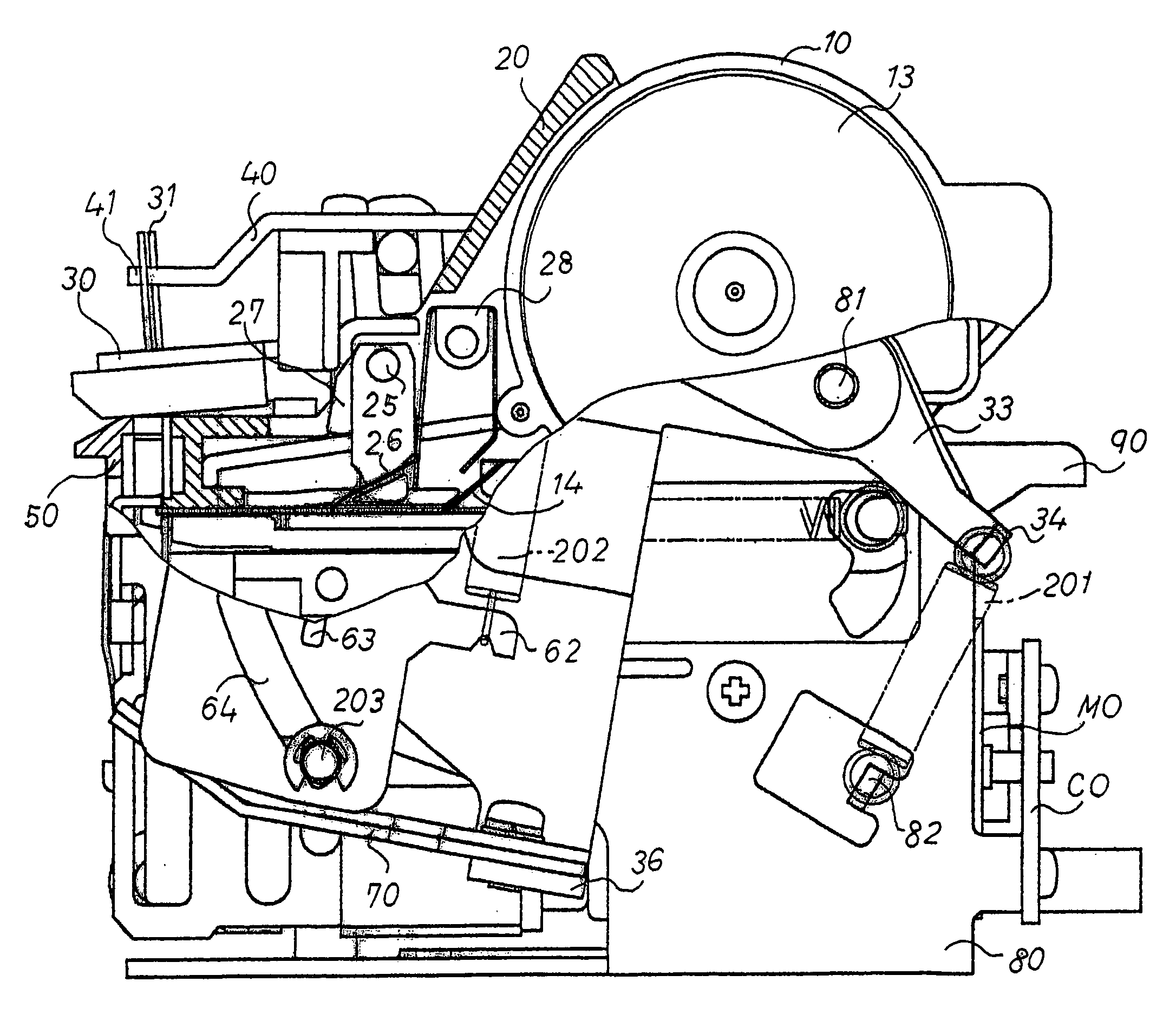
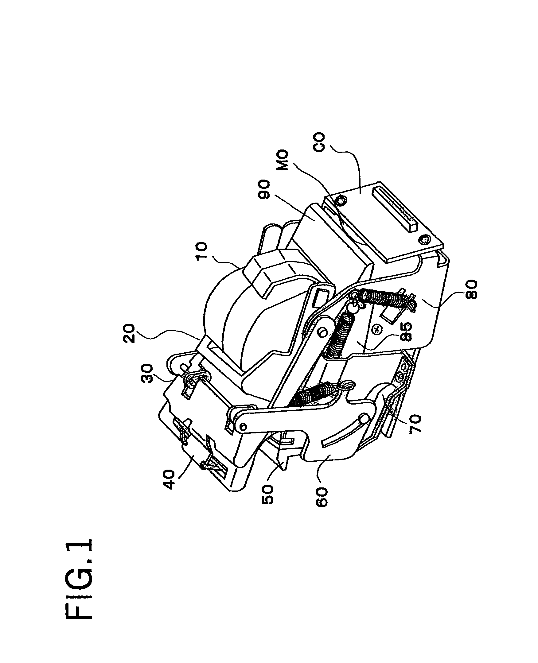
[0045]FIG. 1 shows a plan view of a stapler device, in which 10 is a staple cartridge, 20 is a cartridge holder, 30 is an anvil unit, 40 is a clincher, 50 is a paper guide unit, 60 is a joint lever, 70 is a paper thickness absorbing leaf spring, 80 is a main body frame, 90 is a set lever, MO is a motor, and CO is a connector base.

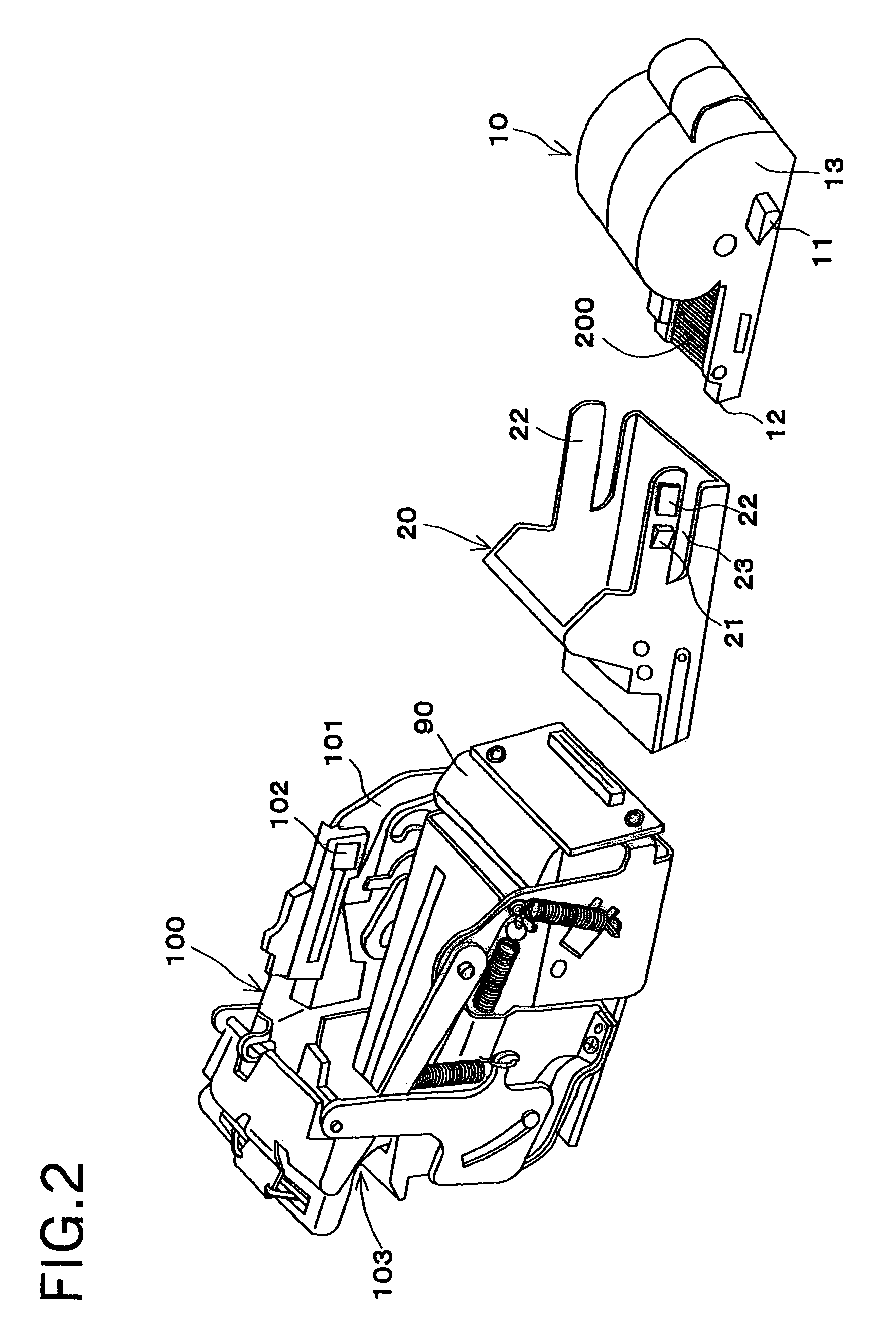
[0046]FIG. 2 is a partially exploded plan view for describing a staple replenishing mechanism of the same stapler device, which comprises a stapler device main body 100, a cartridge holder 20, and a cartridge 10. As the set lever 90 is held down in an installation position, installation knobs 22 on the left and right sides of the cartridge holder 20 are first pinched together, and the cartridge holder 20 is guided by an installation guide 101 of the stapler main body 100 and installed therein. Detents 21 on the cartridge holder 20 are retained in catch holes 102 on the stapler main device 100. By guiding guide protrusions 11 on the cartridge 10 along instal...


PUM


Abstract

A stapler apparatus includes a cartridge that stores staples, a staple driving unit for engaging and driving staples, an urging member to urge the cartridge toward the staple driving unit, and an interlocking mechanism movable upon installation of the cartridge to apply the urging member to the cartridge. The construction provides a stapler apparatus that allows the easy mounting of a cartridge and that can effectively urge a cartridge toward the punching station of the stapler.

Description

BACKGROUND OF THE INVENTION[0001]This invention relates to a stapler device that supports a cartridge storing staples that is detachable therefrom.[0002]Generally, this type of stapler device supports a cartridge storing staples that is detachable therefrom, and is configured such that the cartridge is replaced with a new cartridge when the staples therein are expended.[0003]For example, in the conventional staple devices disclosed in Japanese Patent No. S59-45482 and Japanese Published Patent Application No. H6-206179, when a cartridge is installed therein, the cartridge is first installed in a staple driver unit. After this, the operator must manipulate the cassette so that it engages with a wire-like hook that supports the cartridge. By manually setting the cartridge in the hook, only then will the urging force that urges the cassette toward the staple driver begin to act.SUMMARY OF THE INVENTION[0004]However, in these conventional devices, installing the cartridge involves a two...

Claims


Application Information

Patent Timeline
Patent Type & Authority Patents(United States)
IPC IPC(8): B27F7/38B25C5/15B25C5/16B27F7/36
CPCB27F7/36
Inventor MOCHIZUKI, NAOTOFUKASAWA, TOSHIRO
Owner ACCO BRANDS USA LLC
Why Eureka
Try Eureka