Screw element for same-sense rotating multi-screw extruders

a multi-screw extruder and core radius technology, applied in the direction of rotary stirring mixers, clay mixing apparatus, horizontally mounted tools, etc., can solve the problem of extremely undesirable heat generation of relatively large amounts, and achieve the effect of reducing labor intensity, reducing labor intensity and reducing labor intensity

Inactive Publication Date: 2005-12-13
KRAUSSMAFFEI BERSTORFF GMBH
View PDF7 Cites 11 Cited by
  • Summary
  • Abstract
  • Description
  • Claims
  • Application Information

AI Technical Summary

Benefits of technology

[0015]The action of the screw element according to the invention is such that the material conveyed by the respective multiscrew extruder is drawn into a screw channel, that is to say into the respective cavity between the screw element and the extruder barrel surrounding the screw element, which is bounded by a shearing flight in the sense of a barrier and the cross-sectional volume of which in the conveying direction is reduced to 0, so that the material is forced in its entirety over the shearing flight. Consequently, a defined shearing and stretching takes place for each volume element of the material to be handled. No special back-pressure elements are required to ensure adequately thorough mixing. Therefore, an extruder system equipped with the screw element according to the invention can be readily run empty. Added to this is the fact that the profile of this screw element according to the invention is self-cleaning if it is designed as a closely meshing screw element. On account of these properties, material changes and also color changes can be accomplished particularly quickly and with minimal effort in the case of an extruder system equipped with the screw elements according to the invention.

Problems solved by technology

In particular during the processing of rubber mixes, the generation of relatively large amounts of heat is extremely undesirable.

Method used


Image

  • Screw element for same-sense rotating multi-screw extruders
  • Screw element for same-sense rotating multi-screw extruders
  • Screw element for same-sense rotating multi-screw extruders

Examples


Embodiment Construction

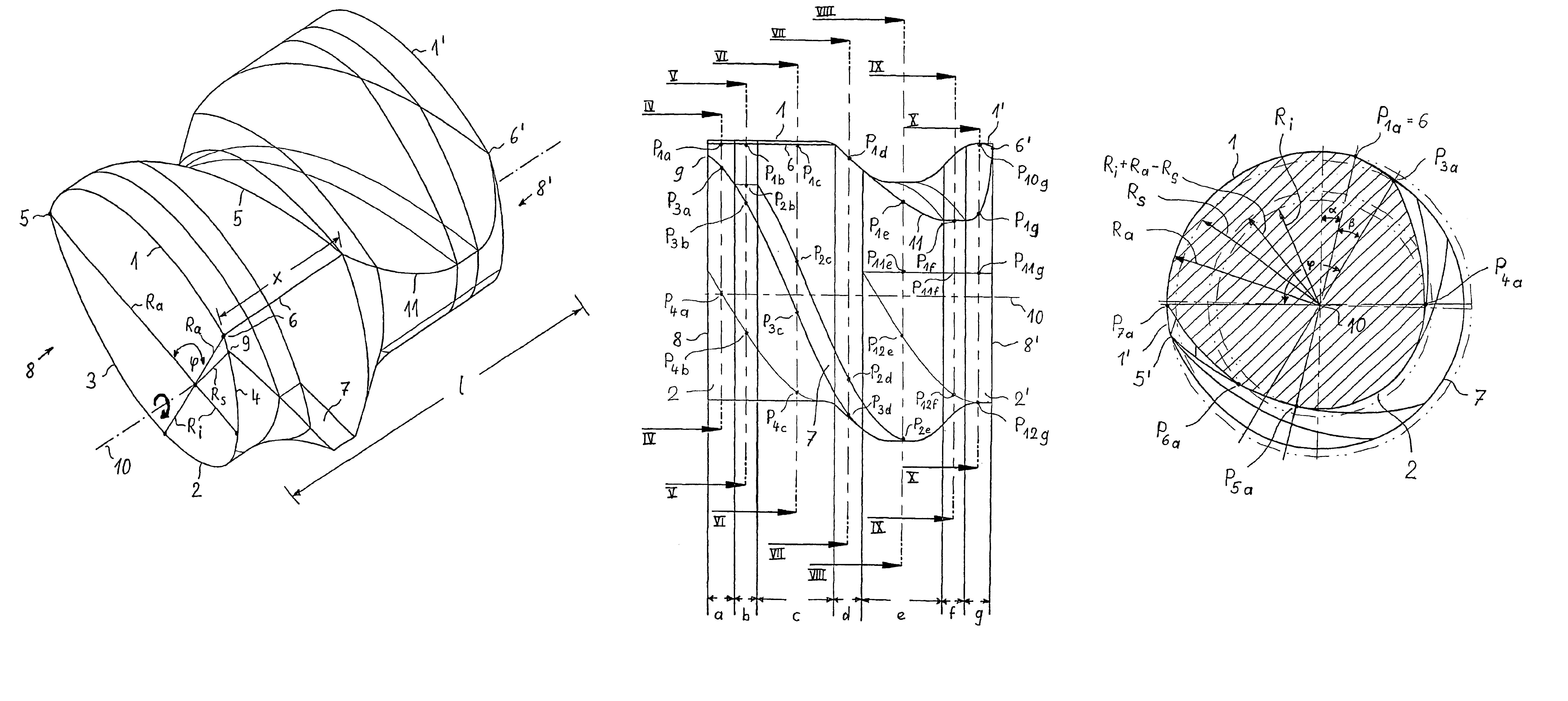
[0032]The screw element according to the invention, shown in FIGS. 1 and 2 in a perspective view from the front right and the front left, respectively (in FIG. 1a and FIG. 2a as a wire model and in FIG. 1b and FIG. 2b as a surface model) is intended for a right-turning screw shaft, as indicated by the thick arrow entered on the front end face 8. The profile of the end face 8 in the chosen exemplary embodiment is that of a closely meshing single-start Erdmenger screw element. The longitudinal axis 10 of the screw element has an axial length 1. Between the points 5, 6, which are also referred to as flight edges, extends the flight 1, which has a surface in the form of a cylinder shell and is formed in the end section as an arc of a circle with the radius Ra about the center point defined by the longitudinal axis 10. The flight width is defined by the flight land angle φ, which is formed between the two radii Ra passing through the left and right flight edges 5, 6, respectively. Diamet...


PUM

PropertyMeasurementUnit
radius Ra+Riaaaaaaaaaa

Abstract

A screw element includes an outer radius Ra and a core radius Ri for multiscrew extruders with co-rotating and intermeshing screw shafts. The screw element has in axial cross section through its longitudinal axis a profile which has at each of the two axial end faces (i.e. a front end face and a rear end face) only one screw flight corresponding to a conventional single-start screw element for intermeshing screw shafts. In this case, the width (flight land angle φ) of the screw flight and conversely, in a corresponding way, the width (flight land angle φ) of the screw flight are formed in a special way and a shearing flight with a constant shearing flight radius Rs, which is greater than Ri, and less than Ra, is provided.

Description

PRIORITY CLAIM[0001]This is a national stage of PCT application No. PCT / DE02 / 00901, filed on 08 Mar. 2002. Priority is claimed on that application and on the following application(s): Country: Germany, Application No.: 101 14 727.9, Filed: 22 Mar. 2001.BACKGROUND OF THE INVENTION[0002]1. Field of the Invention[0003]The invention relates to a screw element with an outer radius Ra and a core radius Ri for multiscrew extruders with co-rotating and intermeshing screw shafts, in particular for twin-screw extruders, which has in axial cross section through its longitudinal axis a profile which has at each of the two axial end faces only a screw flight corresponding to a conventional single-start screw element for intermeshing screw shafts, the surface of which flight, between a left and a right flight edge, is part of a surface of a cylinder with the outer radius Ra, each end face having a circular root with the core radius Ri of the screw shaft and a left and a right flank, which joins t...

Claims


Application Information

Patent Timeline
Patent Type & Authority Patents(United States)
IPC IPC(8): B29B7/42B29C48/595
CPCB29B7/42B29C47/0861B29C47/38B29C47/402B29B7/483B29C47/0844B29C47/6075B29C47/625B29C47/0009B29C48/03B29C48/507B29C48/2517B29C48/395B29C48/402B29C48/65B29B7/482B29B7/489B29C48/40B29C48/595
Inventor UPHUS, REINHARDNOLTING, MATTHIAS
Owner KRAUSSMAFFEI BERSTORFF GMBH
Why Eureka
Try Eureka