Drop ceiling air flow producer

a technology of air flow producer and drop ceiling, which is applied in the field of air flow producer, can solve the problems of exceeding the performance of certain commercially available prior art square units, and achieve the effects of maximizing performance, improving flow rate, and high air flow ra

Inactive Publication Date: 2005-12-13
KEITH LLOYD WALKER
View PDF14 Cites 48 Cited by
  • Summary
  • Abstract
  • Description
  • Claims
  • Application Information

AI Technical Summary

Benefits of technology

[0008]In one aspect, the invention provides a drop ceiling air flow producer adapted to mount in a rectangular seating opening of a drop ceiling framework. The air flow producer comprises a housing with a circular-cylindrical side wall, a closed top and an open bottom. A flow grill overlays the open bottom of the housing, and a fan is supported from within the housing. The fan has a rotary blade assembly centered about a central vertical axis of the housing and operable to discharge air through the grill. A circular flow-separating ring or band is centered about the vertical axis and surrounds the blade assembly. The band defines a generally circular air discharge zone centered in the grill, and an annular air intake zone radially or horizontally outward of the discharge zone. The producer includes a flange with a generally rectangular periphery. The flange extends horizontally outward relative to the side wall of the housing, and conforms in shape to the opening and seating structure. This prevents immediate intake of air from the plenum above the drop ceiling.
[0009]The circular configuration of the producer lends itself to higher air flow rates. It has also been discovered that the circular flow-separating band should be positioned differently than in prior art rectangular producers to maximize performance. In particular, performance of the prior art rectangular producers improves as the band is positioned in the upper half of the housing. In the circular housing configuration of the invention, flows rates improve markedly when the band is located in the lower half of the housing, preferably within 1 or 2 inches inches from the open bottom and the top of the flow grill.

Problems solved by technology

First, it provides a circular drop ceiling air flow producer that can exceed the performance of certain commercially available prior art square units.

Method used


Image

  • Drop ceiling air flow producer
  • Drop ceiling air flow producer
  • Drop ceiling air flow producer

Examples


Embodiment Construction

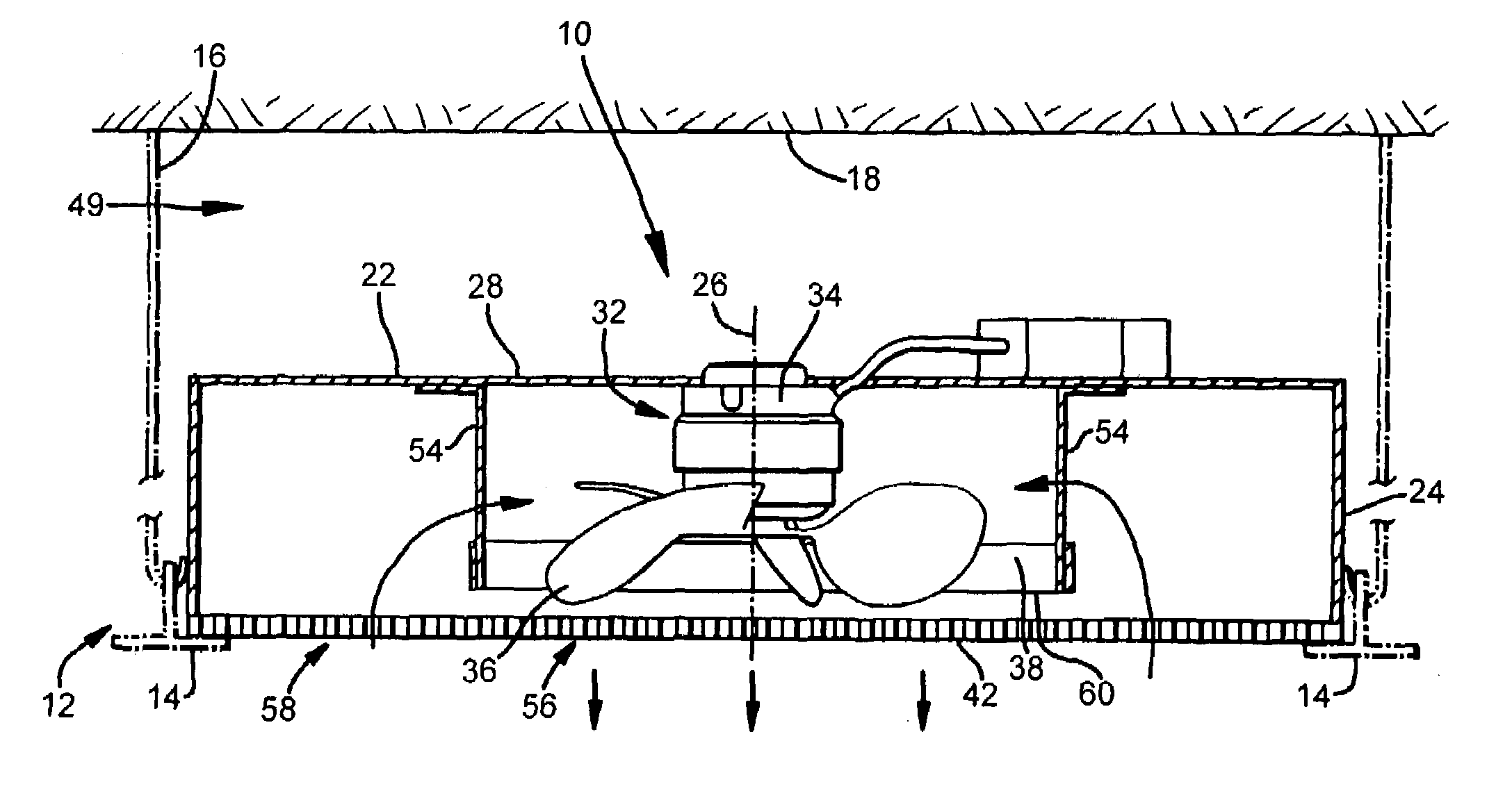
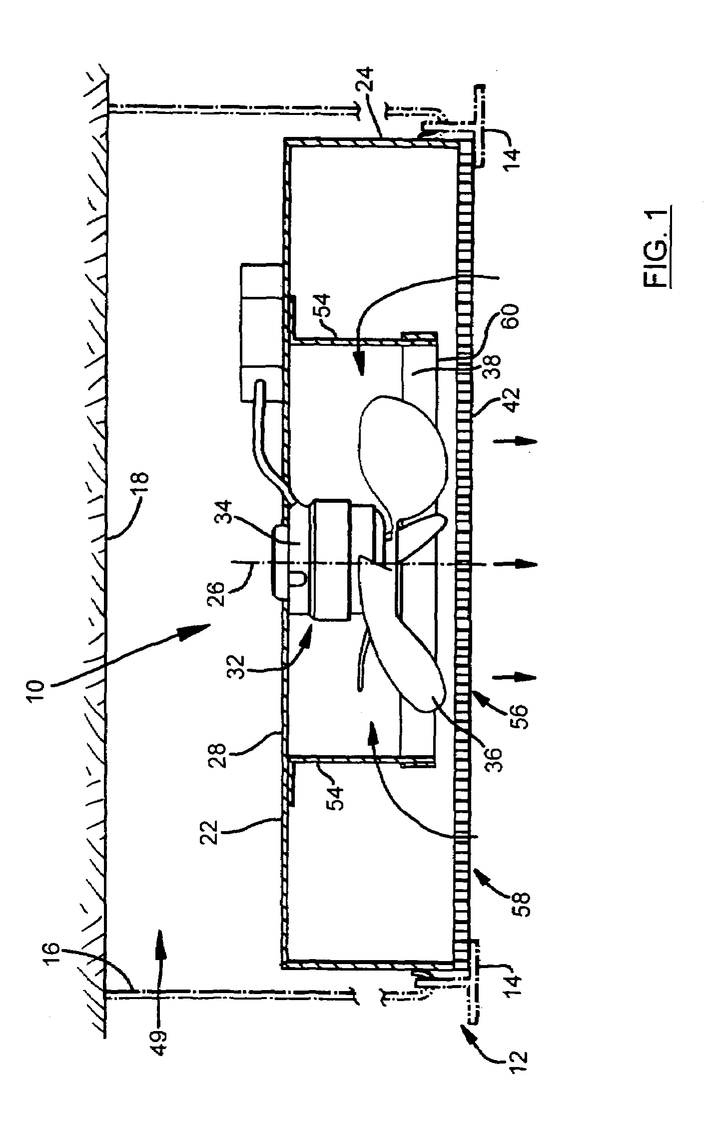
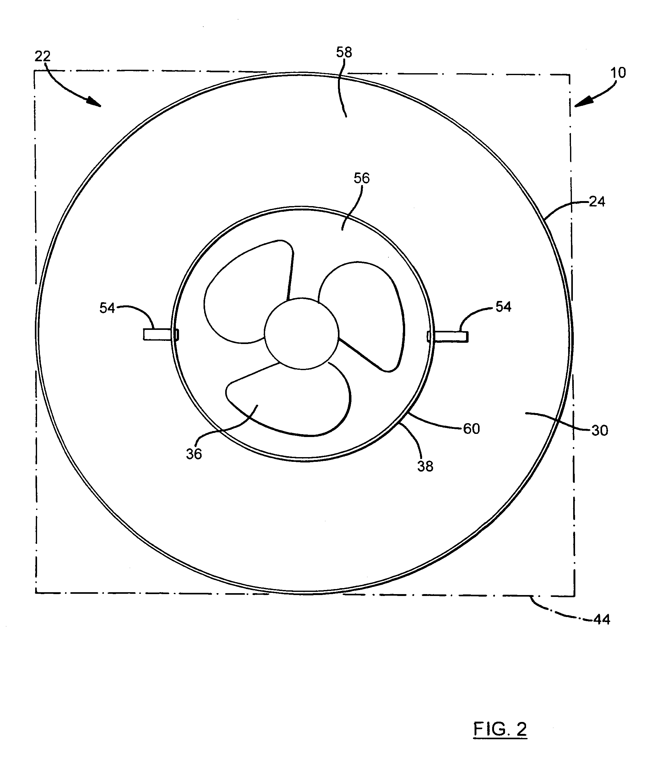
[0017]Reference is made to FIGS. 1–3 which illustrate an air flow producer 10 adapted to produce a high-volume columnar air flow. The producer 10 is specifically adapted for installation in a drop ceiling 12. As most apparent in FIGS. 1 and 3, the drop ceiling 12 comprises a framework of horizontal T-bars 14 and vertical hooks 16 (most apparent in FIG. 3) that support the T-bars 14 from the supradjacent ceiling 18. In this instance, the T-bar framework is adjusted in a conventional manner to define a square opening, generally indicated with reference numeral 20 in FIG. 3, and square seating structure surrounding the opening 20. The producer 10 seats in the opening 20, and draws air from and discharges air below the drop ceiling 12.

[0018]The air flow producer 10 has a generally circular housing 22 constructed of sheet metal. The housing 22 has a circular-cylindrical side wall 24 centered about a vertical axis 26 (shown in FIG. 1), a closed top 28 and an open bottom 30. The side wall ...


PUM


Abstract

An air flow producer of non-rectangular shape is adapted for installation in a rectangular opening of a drop ceiling. In preferred form, the producer has a circular housing with an open bottom covered with a grill. A fan with a rotary blade assembly is mounted in the housing to produce a downward air flow, and a circular metal band surrounding the rotary blade assembly defines an air discharge zone centered in the grill and an annular air intake zone surrounding the discharge zone. Flow rates are optimized by positioning the band close to the grill. The grill is preferably integrally molded with a rectangular flange that seats in the drop ceiling opening. The flange supports the housing from the framework and closes the opening to prevent the producer from drawing air from the plenum above the drop ceiling.

Description

FIELD OF THE INVENTION[0001]The invention relates generally to air flow producers for reducing temperature gradients in a room, and, more specifically, to air flow producers adapted for installation in drop ceilings.BACKGROUND OF THE INVENTION[0002]It is well known that warm air forced into a room or derived from radiators tends to rise toward the ceiling of a room while cooler air tends to accumulate near the floor. This produces a temperature gradient that exposes individuals to colder room air during winter months and increases heat loss through ceilings and roofs. A corresponding problem arises during summer months. Individuals may experience a room as being hot because cool air discharged from air conditioning units tends to settle to the floor. Thermostat setting are often changed to obtain more heat or more cool air. In either case, the net result is increased energy consumption and higher cooling and heating costs.[0003]It is also well known that ceiling fans can reduce room...

Claims


Application Information

Patent Timeline
Patent Type & Authority Patents(United States)
IPC IPC(8): F24F7/007F24F13/06
CPCF24F7/007F24F2013/0616F24F2221/14
Inventor WALKER, KEITH LLOYDMONRO, ALAN RICHARDKOZLOWSKI, CHRISTOPHER HENRY
Owner KEITH LLOYD WALKER
Why Eureka
Try Eureka