Contactor device of circuit breaker

a circuit breaker and contactor technology, applied in the direction of circuit-breaking switch contacts, circuit-breaking switches, contact mechanisms, etc., can solve the problem of large driving force, achieve the effect of reducing the moment of inertia, increasing the opening speed, and increasing the driving for

Inactive Publication Date: 2005-12-13
FUJI ELECTRIC FA COMPONENTS & SYST CO LTD
View PDF16 Cites 9 Cited by
  • Summary
  • Abstract
  • Description
  • Claims
  • Application Information

AI Technical Summary

Benefits of technology

[0008]In the first aspect of the invention, the first movable contactor is opened and closed by the open-close mechanism, and has the movable contact at the one end thereof and is rotatably supported at the other end thereof, thereby reducing a load relative to the open-close mechanism. The first movable contactor has the movable contact at the one end thereof, and the second movable contactor has the movable contacts at both ends thereof. Accordingly, the contactor device has a simple structure and does not occupy a large space in a height direction.
[0010]According to a third aspect of the present invention, the second movable contactor may be arranged such that the supporting point thereof is located at the center between the first and second movable contacts. With this structure, it is possible to decrease moment of inertia of the second movable contactor, thereby increasing an opening speed.
[0011]According to a fourth aspect of the present invention, the second movable contactor may be arranged such that the supporting point thereof is located closer to the second movable contact between the first and second movable contacts. With this structure, the second movable contact contacts with a force larger than that of the first movable contact. Accordingly, when the circuit breaker is closed in a normal state, it is possible to reduce an impact on the second movable contactor from the first movable contactor and prevent the second movable contact from moving upwardly away from the fixed contact.
[0012]According to a fifth aspect of the present invention, a long hole for loosely holding a supporting point shaft of the second movable contactor may be formed in a holding member holding the supporting point shaft that supports the second movable contactor. The long hole extends along a circular arc passing through the supporting point shaft around the second movable contact. With this structure, when the circuit breaker is closed in a normal state, it is possible to absorb an impact on the second movable contactor from the first movable contactor through a movement of the supporting point shaft in the long hole and prevent the second movable contact from moving upwardly away from the fixed contact.
[0013]According to a sixth aspect of the present invention, the second movable contactor may be provided with an auxiliary contact spring for pressing the second movable contact against the fixed contact. With the auxiliary contact spring, it is possible to prevent the second movable contact from moving upwardly due to the impact described above.
[0014]According to the invention, it is possible to make the double-break circuit breaker with superior breaking performance small and to reduce the load of the open-close mechanism similar to a single-break circuit breaker.

Problems solved by technology

With this structure, the electromagnetic repulsive force is generated between the contacts and between parallel conductor portions, thereby obtaining large driving force.

Method used


Image

  • Contactor device of circuit breaker
  • Contactor device of circuit breaker
  • Contactor device of circuit breaker

Examples


Embodiment Construction

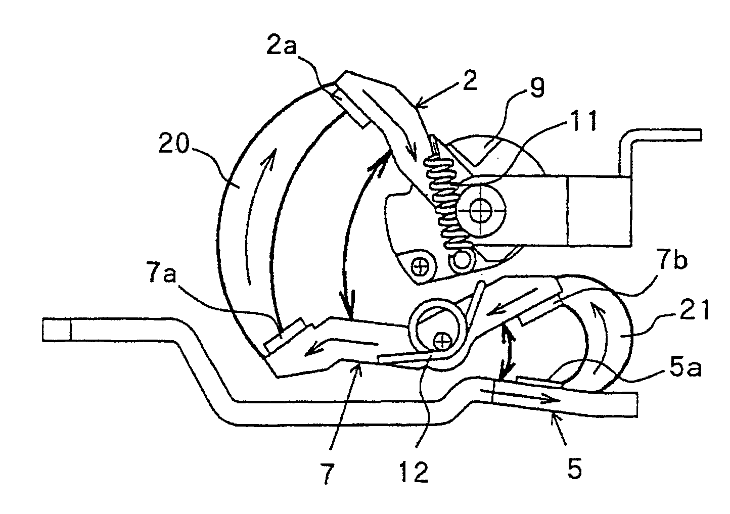
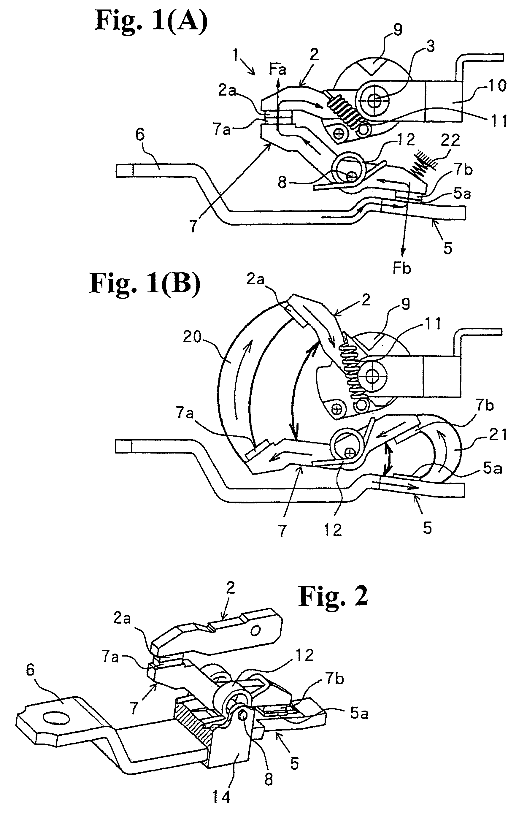
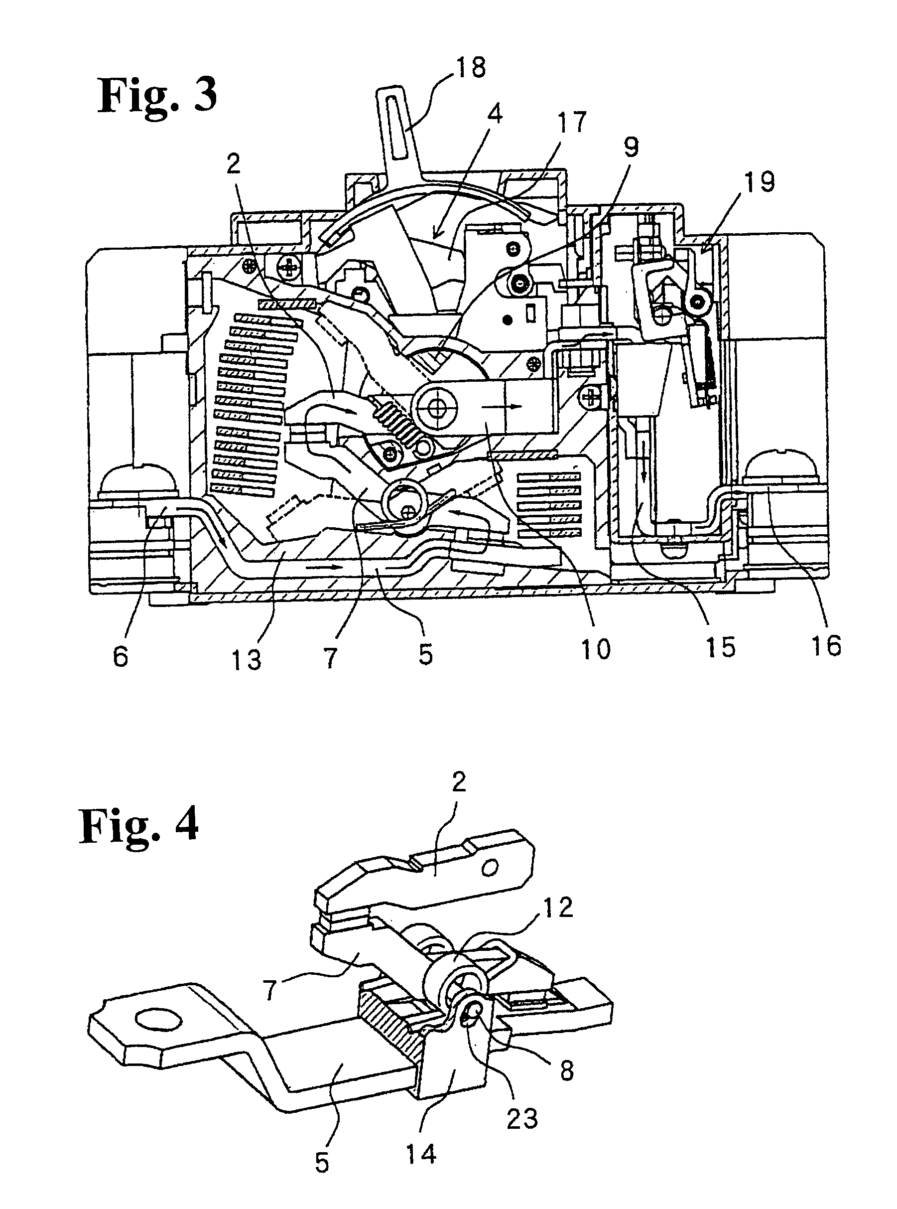
[0020]Hereunder, embodiments of the present invention will be described with reference to the accompanying drawings. FIGS. 1A and 1B are views showing a contactor device according to an embodiment of the present invention, wherein FIG. 1A is a side view thereof in a closed state and FIG. 1B is a side view thereof in an open state. FIG. 2 is a perspective view of the contactor device shown in FIGS. 1A and 1B. FIG. 3 is a vertical sectional view of a circuit breaker (molded case breaker) having the contactor device shown in FIGS. 1A and 1B.

[0021]As shown in FIGS. 1A, 1B and 2, a contactor device 1 is provided with a first movable contactor 2, a fixed contactor 5, and a second movable contactor 7. The first movable contactor 2 has a movable contact 2a at one end thereof (left end in FIG. 1B), and is rotatably supported by a supporting point shaft 3 at the other end thereof (right end in FIG. 1B). An open-close mechanism 4 drives the first movable contactor 2 to open and close (see FIG....


PUM


Abstract

A contactor device of a repulsion-type circuit breaker includes a first movable contactor with a first movable contact to be driven by an open-close mechanism; a fixed contactor; a second movable contactor having second and third movable contacts; a first contact spring for urging the first movable contactor toward the second movable contactor; and a second contact spring for urging the second movable contactor toward the first movable contactor and the fixed contactor. The first movable contactor, fixed contactor, and second movable contactor are arranged such that when an over-current flows, an electromagnetic repulsive force is generated so that the first and second movable contactors are rotated against the first and second contact springs to open between the first movable contact and the second movable contact and between the fixed contact and the third movable contact before the open-close mechanism opens the first movable contact.

Description

BACKGROUND OF THE INVENTION AND RELATED ART STATEMENT[0001]The present invention relates to a contactor device of a repulsion-type circuit breaker in which a movable contactor rotates with an electromagnetic repulsive force to open contacts.[0002]A repulsion-type circuit breaker includes a double-break circuit breaker in which two movable contacts are separated simultaneously and a single-break circuit breaker in which one movable contact is separated. The double-break circuit breakers are disclosed in, for example, Japanese Patent Publications (Kokai) No. 06-52777 and No. 03-182028, and Japanese Utility Model Publication (Kokai) No. 52-45164. The single-break circuit breakers are disclosed in, for example, Japanese Patent Publications (Kokai) No. 04-190535 and No. 03-34234.[0003]In the circuit breaker disclosed in Japanese Patent Publication (Kokai) No. 06-52777, an open-close mechanism drives a movable contactor having movable contacts at both ends to open and close, and the open-...

Claims


Application Information

Patent Timeline
Patent Type & Authority Patents(United States)
IPC IPC(8): H01H9/40H01H73/02H01H73/04H01H73/18H01H73/38H01H75/00H01H75/10H01H77/10
CPCH01H9/40H01H77/10H01H1/2041H01H77/102
Inventor SATO, AKIFUMIASAKAWA, KOJIMITSUSHIGE, MITSUHIROTAKAHASHI, YASUHIROYAMAGATA, HIDETO
Owner FUJI ELECTRIC FA COMPONENTS & SYST CO LTD
Why Eureka
Try Eureka