
Methods and apparatus for monitoring gas turbine combustion dynamics

a gas turbine and combustion dynamics technology, applied in the field of gas turbine engines, can solve problems such as mechanical failures and/or shutdowns, failure of other hot gas path components, and reducing the service life of the combustor

Inactive Publication Date: 2005-12-20
GENERAL ELECTRIC CO
View PDF19 Cites 37 Cited by
  • Summary
  • Abstract
  • Description
  • Claims
  • Application Information

AI Technical Summary

Benefits of technology

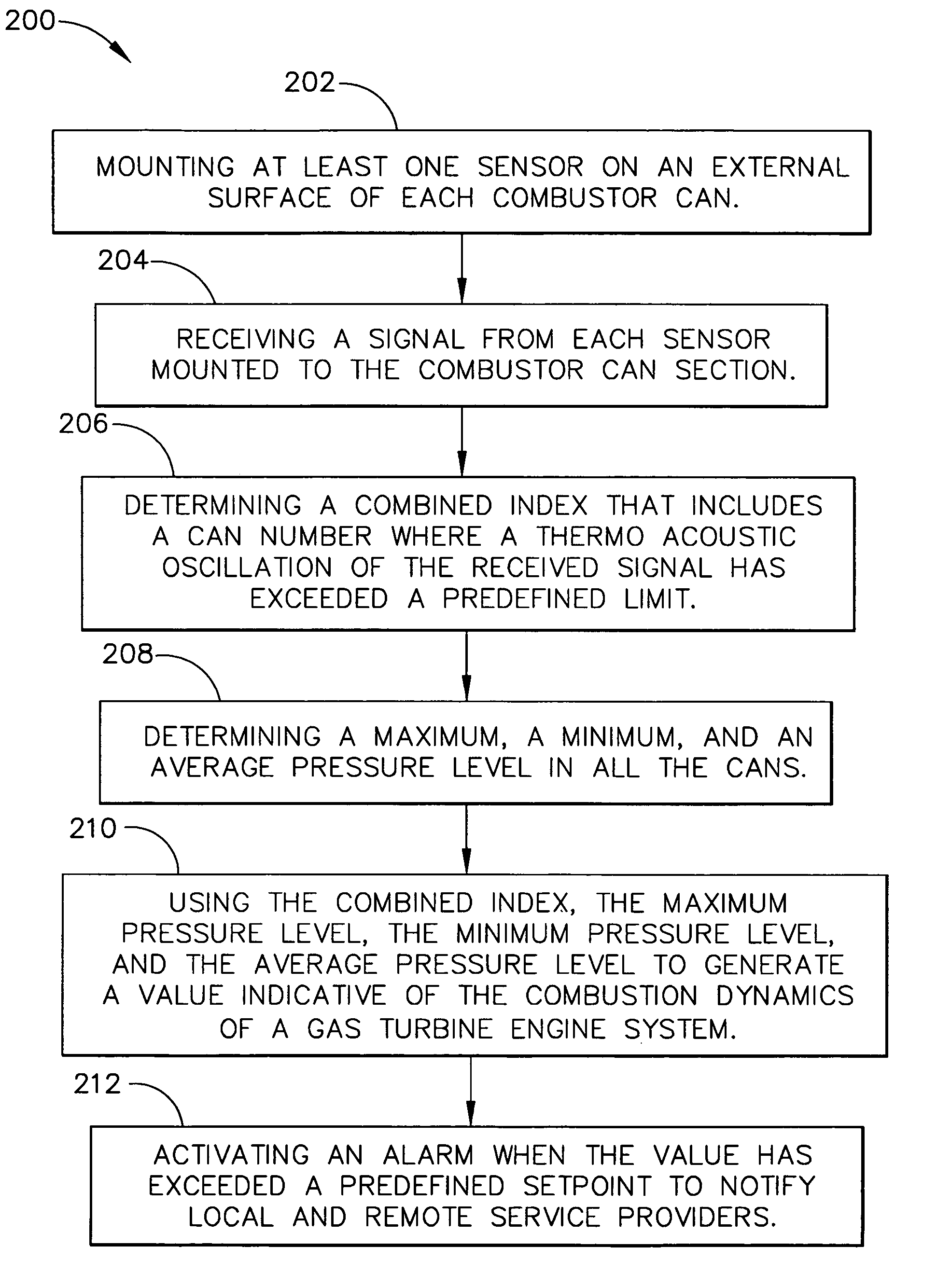
[0005]In one aspect, a method for monitoring and diagnosing the combustion dynamics of a gas turbine engine system is provided. The method includes mounting at least one sensor on an external surface of at least one combustor can, receiving a signal from the sensor mounted to the combustor can, validating an accuracy of the signal from the sensors, determining the combustion dynamics of the can based on the received signals, and generating an indication when a combustion dynamic threshold has been exceeded.

Problems solved by technology

While using DLN techniques facilitates generating a reduced quantity of NOx, the lean fuel / air mixture supplied to the gas turbine may also cause combustion instabilities, such as oscillations, which may result in mechanical failures and / or shutdowns.
Relatively high oscillation frequencies may cause combustor fatigue thereby reducing the service life of the combustor, or may also cause other hot gas path components to fail.
However, once the transducers are removed, direct combustion dynamics information is not available to the operator until the next scheduled tuning.

Method used


Image

  • Methods and apparatus for monitoring gas turbine combustion dynamics
  • Methods and apparatus for monitoring gas turbine combustion dynamics
  • Methods and apparatus for monitoring gas turbine combustion dynamics

Examples


Embodiment Construction

[0012]While the methods and apparatus are herein described in the context of a gas turbine engine used in an industrial environment, it is contemplated that the herein described method and apparatus may find utility in other combustion turbine systems applications including, but not limited to, turbines installed in aircraft. In addition, the principles and teachings set forth herein are applicable to gas turbine engines using a variety of combustible fuels such as, but not limited to, natural gas, gasoline, kerosene, diesel fuel, and jet fuel. The description hereinbelow is therefore set forth only by way of illustration rather than limitation.

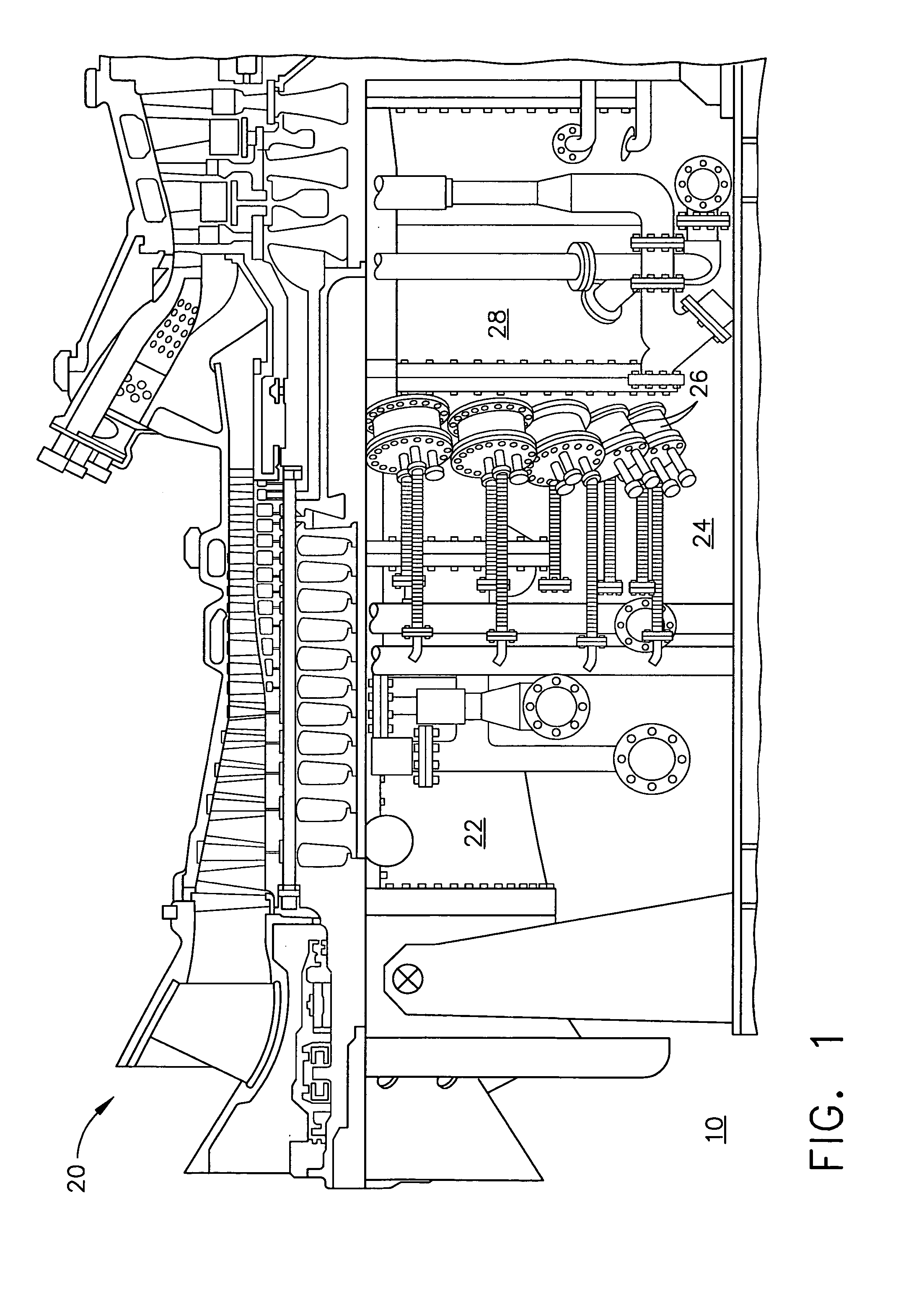
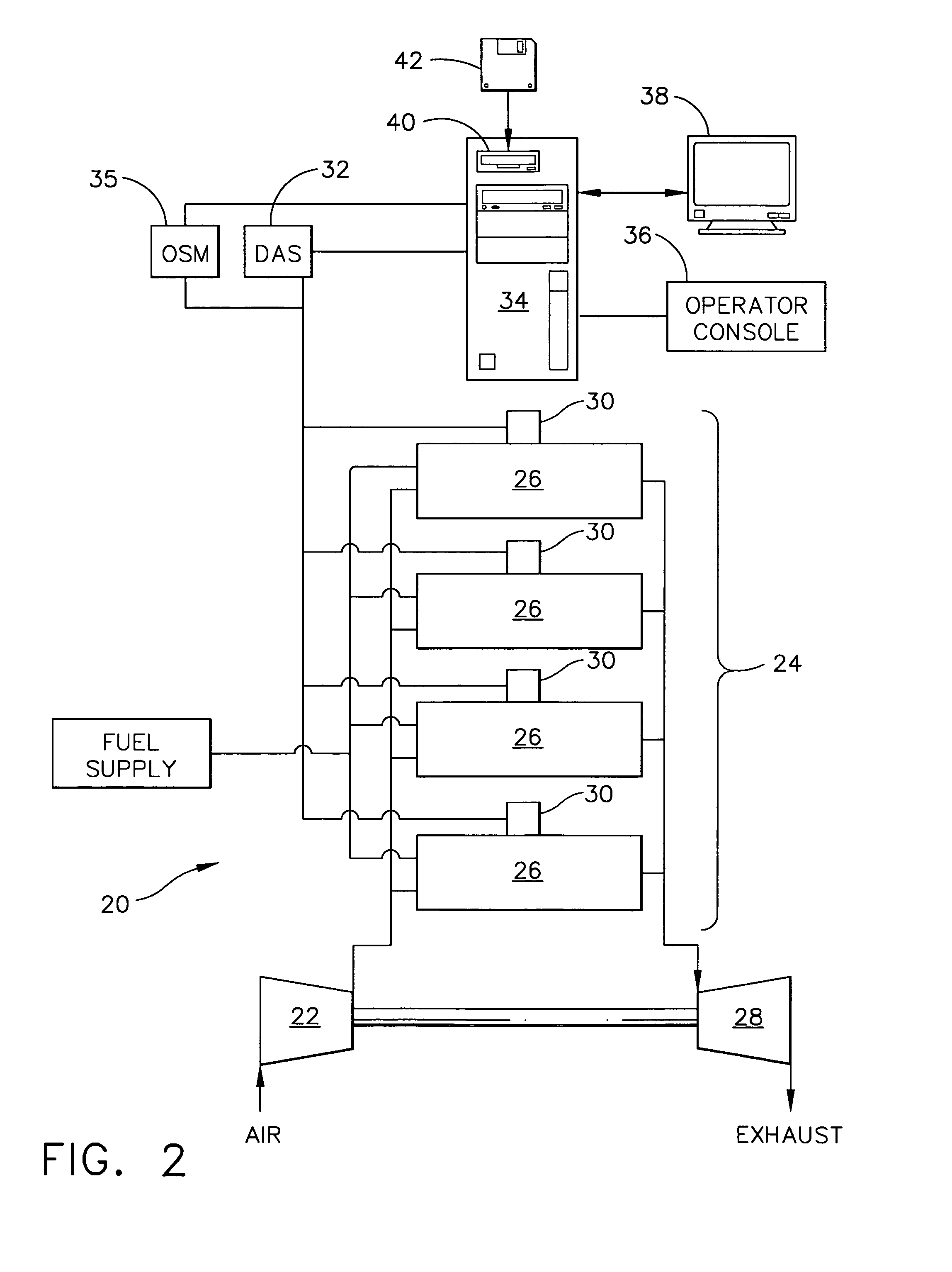
[0013]FIG. 1 is a side cutaway view of a gas turbine system 10 that includes a gas turbine 20. Gas turbine 20 includes a compressor section 22, a combustor section 24 including a plurality of combustor cans 26, and a turbine section 28 coupled to compressor section 22 using a shaft (not shown).

[0014]In operation, ambient air is channeled into...


PUM


Abstract

A method for monitoring and diagnosing the combustion dynamics of a gas turbine engine system includes mounting at least one sensor on an external surface of at least one combustor can, receiving a signal from the sensor mounted to the combustor can, validating an accuracy of the signal from the sensors, determining the combustion dynamics of the can based on the received signals, and generating an indication when a combustion dynamic threshold has been exceeded.

Description

BACKGROUND OF THE INVENTION[0001]This invention relates generally to gas turbine engines, and more particularly, to methods and apparatus for monitoring gas turbine engines.[0002]Gas turbine engines typically include a compressor section, a combustor section, and at least one turbine section. The compressor compresses air which is mixed with fuel and channeled to the combustor. The mixture is then ignited generating hot combustion gases. The combustion gases are channeled to the turbine which extracts energy from the combustion gases for powering the compressor, as well as producing useful work to power a load, such as an electrical generator, or to propel an aircraft in flight.[0003]Gas turbine engines operate in many different operating conditions, and stable combustion facilitates engine operation over a wide range of engine operating conditions. More specifically, stable combustion facilitates reducing engine blowout while achieving engine rated thrust or power levels. Furthermo...

Claims


Application Information

Patent Timeline
Patent Type & Authority Patents(United States)
IPC IPC(8): F02C9/00
CPCF02C9/00
Inventor CATHARINE, DOUGLAS ANCONAGLEESON, EAMONDE, SOUMEN
Owner GENERAL ELECTRIC CO
Learn More