
Transport system for articles, in particular containers for baggage pieces, and control method for the transport system

a technology for transporting systems and articles, which is applied in the direction of mechanical conveyors, conveyor parts, packaging, etc., can solve the problems of slowed article flow and elevator operation, and achieve the effect of high article transport ra

Inactive Publication Date: 2005-12-20
SIEMENS AG
View PDF19 Cites 11 Cited by
  • Summary
  • Abstract
  • Description
  • Claims
  • Application Information

AI Technical Summary

Benefits of technology

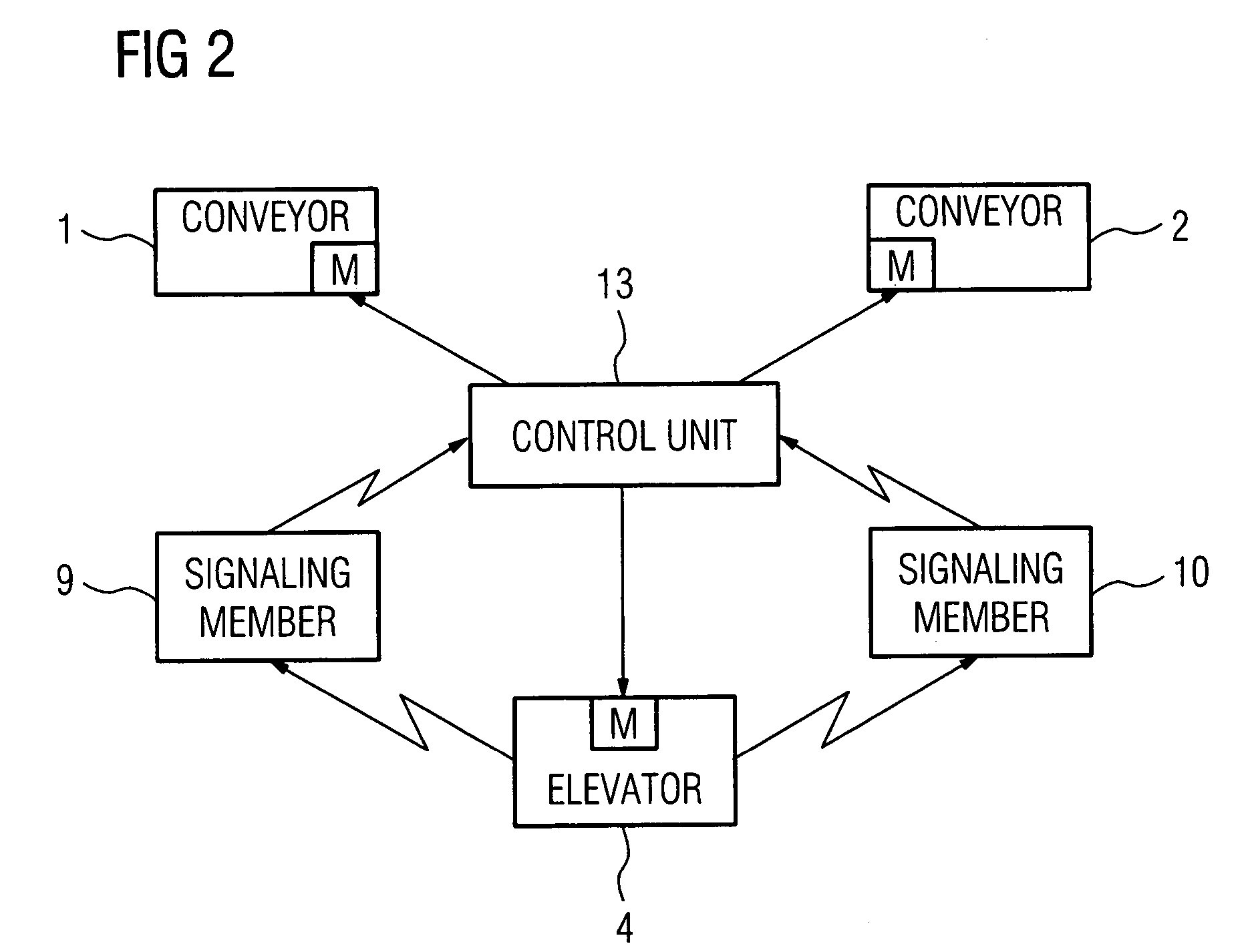
"The present invention provides a transport system for articles, in particular containers for baggage pieces, which includes at least two conveyors disposed in vertically spaced-apart planes to define an upper conveyor and a lower conveyor. An elevator is movable in a vertical direction between a lower end position in which it is aligned with the lower conveyor to form a lower transport path for transfer of articles from the lower conveyor to the elevator, and an upper end position in which it is aligned with the upper conveyor to form an upper transport path for transfer of articles from the upper conveyor to the elevator. A control unit is provided to control the transfer of the articles from the conveyors to the elevator and from the elevator to the conveyors in dependence on the vertical position of the elevator. The elevator conveyor runs before the elevator reaches the end positions, and each of the conveyors and the elevator includes a continuous conveyor belt and a drive motor for operating the conveyor belt. The control unit can be constructed to initiate the movement of the articles after a predetermined delay time. The technical effect of the invention is to provide a high-speed transport system for articles that allows for efficient transfer of articles between the conveyors and the elevator."

Problems solved by technology

A transport system of this type has the drawback that the flow of articles is slowed down by the operation of the elevator.

Method used


Image

  • Transport system for articles, in particular containers for baggage pieces, and control method for the transport system
  • Transport system for articles, in particular containers for baggage pieces, and control method for the transport system
  • Transport system for articles, in particular containers for baggage pieces, and control method for the transport system

Examples


Embodiment Construction

[0015]Throughout all the Figures, same or corresponding elements are generally indicated by same reference numerals. These depicted embodiments are to be understood as illustrative of the invention and not as limiting in any way. It should also be understood that the drawings are not necessarily to scale and that the embodiments are sometimes illustrated by graphic symbols, phantom lines, diagrammatic representations and fragmentary views. In certain instances, details which are not necessary for an understanding of the present invention or which render other details difficult to perceive may have been omitted.

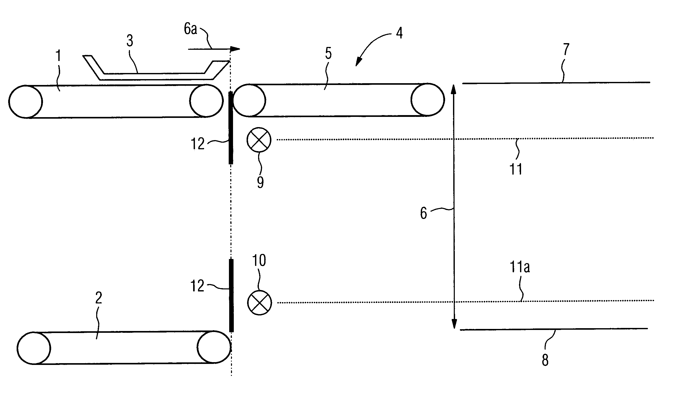
[0016]Turning now to the drawing, and in particular to FIG. 1, there is shown a schematic illustration of a transport system according to the present invention, including two fixed conveyors 1, 2, which are superposed in a vertical direction in spaced-apart planes, and an elevator 4 which is disposed next to the conveyors 1, 2 (in FIG. 1 to the right of the conveyors 1, 2) and...


PUM


Abstract

A transport system for articles includes an upper conveyor and a lower conveyor, and an elevator having an elevator conveyor and movable in a vertical direction between a lower end position in which the elevator conveyor is in alignment with the lower conveyor, and an upper end position in which the elevator conveyor is in alignment with the upper conveyor. The transfer of the articles between the conveyors and the elevator conveyor is controlled by a control unit which cooperates with a signaling assembly including a first signaling member associated to one plane for indicating that the elevator has reached an upper trigger position during movement from the lower end position to the upper end position, and a second signaling member associated to the other plane for indicating that the elevator has reached a lower trigger position during movement from the upper end position to the lower end position.

Description

CROSS-REFERENCES TO RELATED APPLICATIONS[0001]This application claims the priority of German Patent Application, Serial No. 102 55 344.0, filed Nov. 27, 2002, pursuant to 35 U.S.C. 119(a)–(d), the disclosure of which is incorporated herein by reference.BACKGROUND OF THE INVENTION[0002]The present invention relates to a transport system for articles, in particular containers for baggage pieces. The present invention further relates to a control method for such a transport system.[0003]Conventional transport systems for articles are known which include two or more conveyors, superposed in vertically spaced-apart planes, and an elevator, bridging the distance between the conveyors and having a horizontal elevator conveyor to form a transport path with the upper conveyor and a transport path with the lower conveyor. The articles are transferred in conveying direction of the respective transport path either from the elevator to the conveyors or, vice versa, from the conveyors to the elev...

Claims


Application Information

Patent Timeline
Patent Type & Authority Patents(United States)
IPC IPC(8): B65G47/57B65G47/64
CPCB65G47/57B65G47/643B65G2201/0258B65G2201/0264
Inventor BRIXIUS, WOLFGANGGRAFER, DOMINIKHOENE, ALBRECHT
Owner SIEMENS AG
Learn More