
Paper shredding vehicle

Inactive Publication Date: 2005-03-10
NAKABAYASHI CORP
View PDF5 Cites 11 Cited by
  • Summary
  • Abstract
  • Description
  • Claims
  • Application Information

AI Technical Summary

Benefits of technology

[0007] The present invention has been developed in view of the above problems and it is an object of the present invention to provide a vehicle with a paper shredder which maintains confidentiality while shredding confidential documents, improves compaction ratio of shreds and provides a high transportation efficiency.
[0016] Since the vehicle with a paper shredder of one embodiment of the present invention goes to a location of confidential documents to shred them, the confidentiality of the documents is securely protected. Since the container on the loading platform provides a closed space, nobody can view the documents from outside. Since the document papers are not blown away by sudden wind, confidentiality is assured.
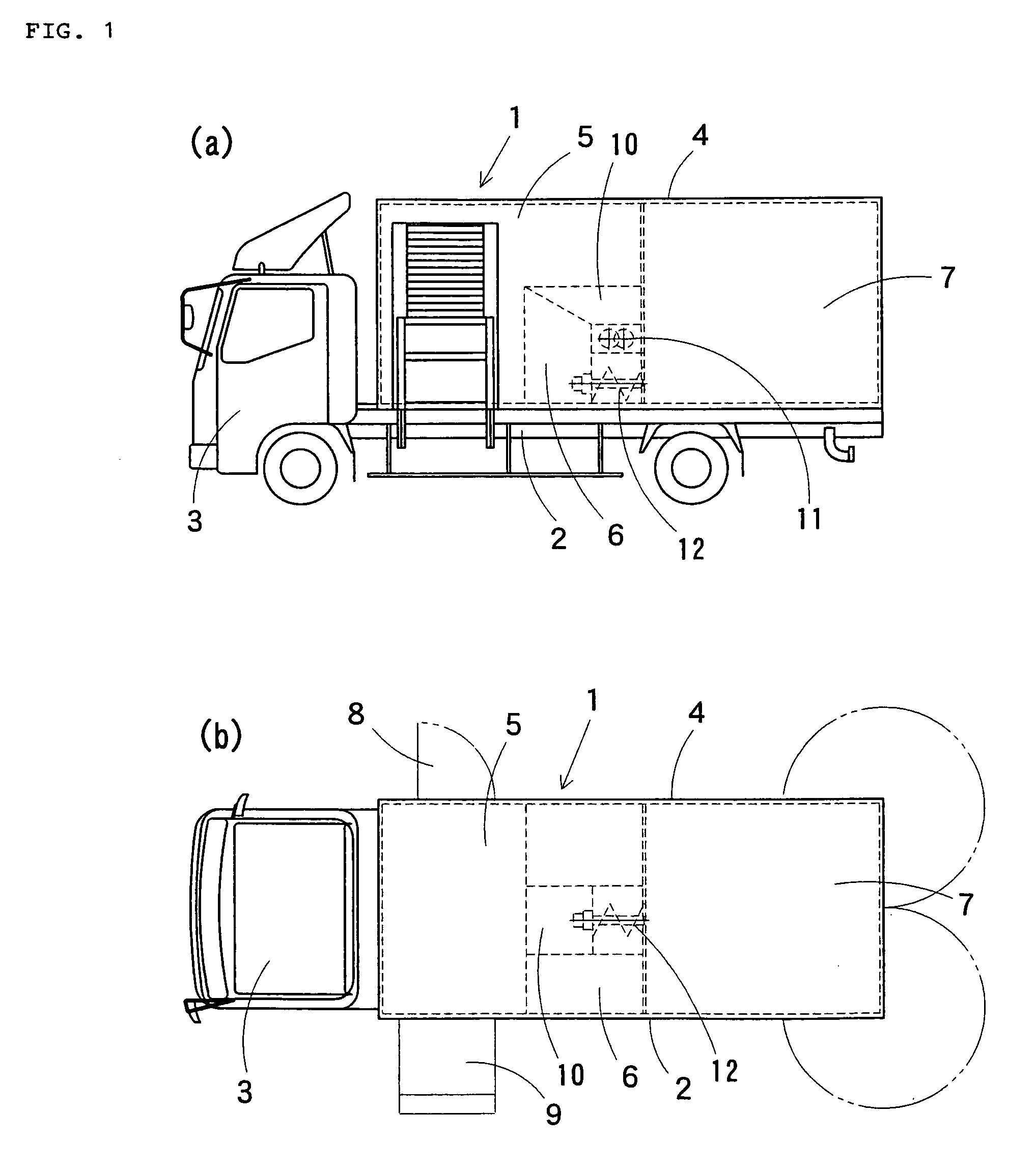
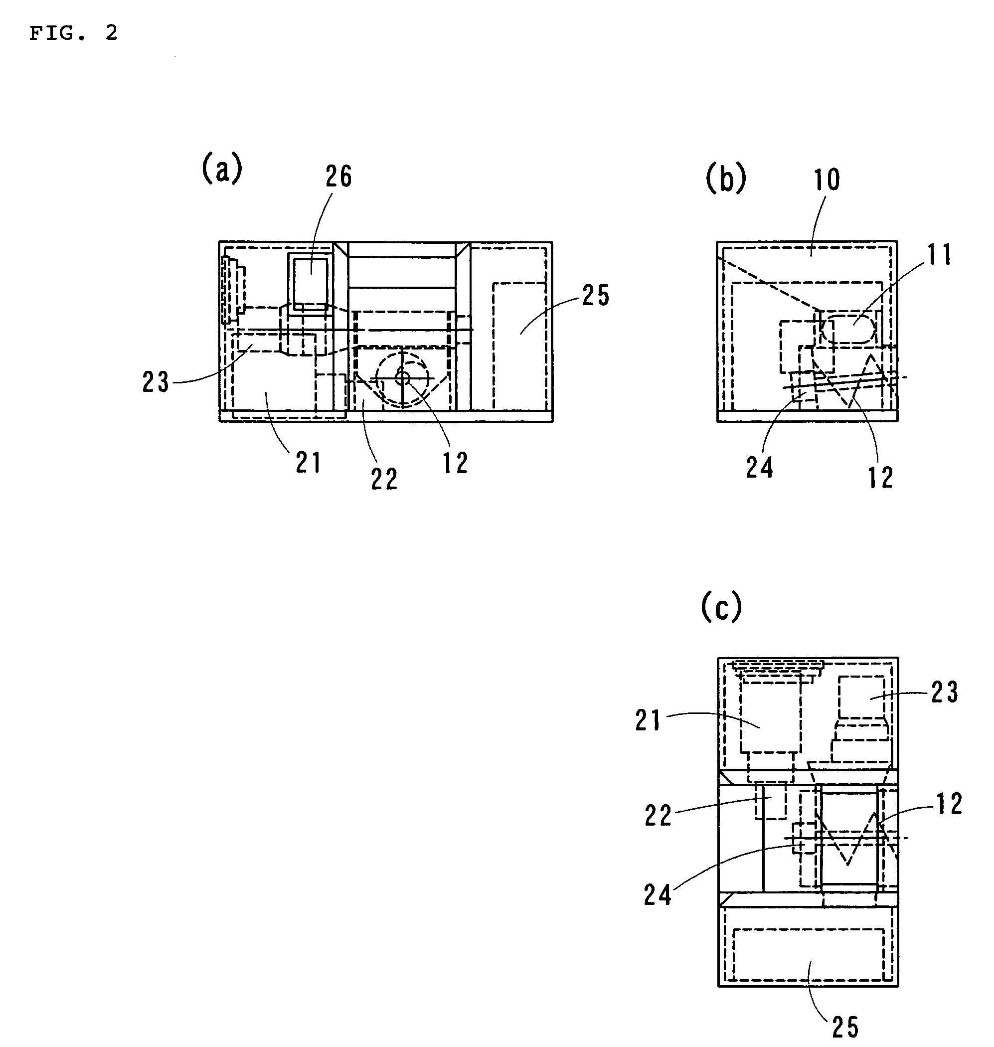
[0017] Since the internal space of the container is partitioned into the shredding operation chamber, the shredder chamber, and the shred storage chamber in the order in a direction from the front of the vehicle, a heavy machine section is installed at the approximate center of the vehicle. The vehicle is thus well balanced even when the vehicle is running.
[0018] The conveyance and compaction unit has the discharge port opened at the level of the floor of the shred storage chamber, and the driving shaft of the screw conveyor is tilted up in a backward direction at an angle within a range from 0 to 5 degrees with respect to the floor of the shredder chamber. This arrangement enhances the effect of compaction of the strips in horizontal and vertical directions. Compaction forces in the horizontal and vertical directions are thus effectively applied.
[0020] Since the four walls of the shred storage chamber are constructed of reinforcement flat panels, the strips are smoothly discharged and condensation is allowed to drop downward easily.
[0021] Since the floor of the shred storage chamber is covered with a sheet of steel, the shreds are easily discharged using a forklift. If the floor is constructed of the belt conveyor, the shreds are easily discharged.

Problems solved by technology

Since space available for storage of documents is limited, such documents are shredded after a predetermined retention period of time.
However, shredded documents are bulky, typically 10 times as large as the original volume of the documents.
For this reason, transportation costs for transporting shredded documents to a paper manufacturing company for dissolving the shreds for recycling are too high, and the recycling business is not profitable.
The vehicle with a paper shredder disclosed in Japanese Utility Model No. 3018367 is used in processing general papers and is not intended to recycle used sheets of paper.
The paper processing vehicle disclosed in Japanese Unexamined Patent Application Publication No. 10-305902 includes a paper processing apparatus which is intended to recycle resources in a wide range, requires sorting and collecting means for sorting and collecting shreds and is complex in structure leading to high manufacturing costs.
Debris must be packed in bags and packing efficiency of the debris is low.
Although this kind of vehicle includes a conveyor, a pusher and a compactor, its structure is complex, leaving a problem of high manufacturing costs.
But the packing efficiency is still low.

Method used


Image

  • Paper shredding vehicle
  • Paper shredding vehicle
  • Paper shredding vehicle

Examples


Embodiment Construction

[0030] A vehicle with a paper shredder 1 according to the present invention is described below with reference to the drawings.

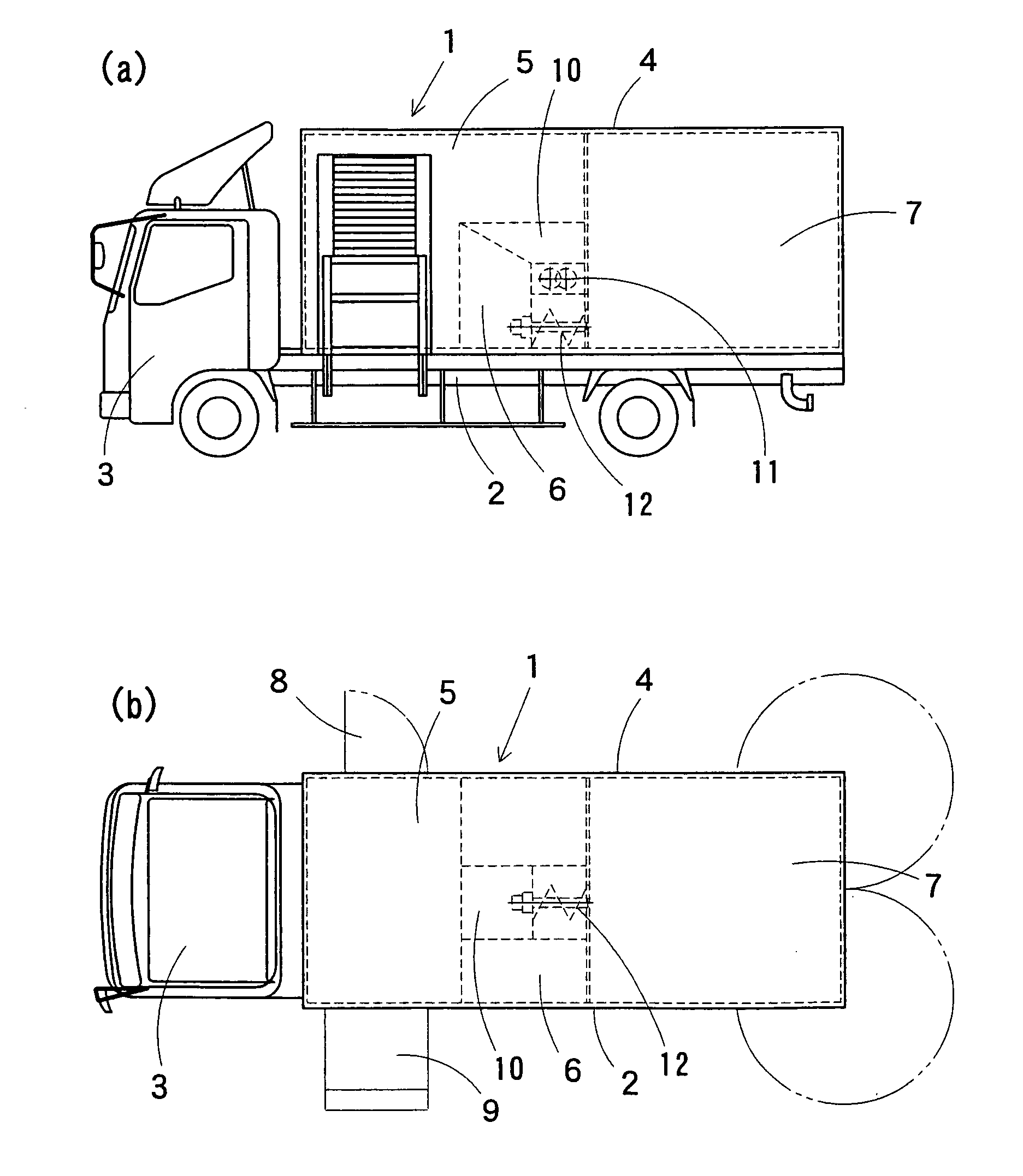
[0031]FIG. 1 (a) is a side view of the vehicle with a paper shredder of a first embodiment of the present invention and FIG. 1 (b) is a plan view of the vehicle. As shown, the vehicle 1 includes a loading platform 2 on the back portion thereof and a driver's cab section 3 on the front portion thereof. A box-like vehicle body 4 defining a closed space having a predetermined size is mounted on the loading platform 2. The internal space of the vehicle body 4 is partitioned into three sections, namely, a shredding operation chamber 5, a shredder chamber 6 and a shred storage chamber 7.

[0032] The shredding operation chamber 5 provides space within which operators work and has a side door 8 on an entrance on the right-hand side thereof viewed from the front of the vehicle and a side lift 9 on the left-hand side thereof for introducing papers (such as confidential...


PUM


Abstract

A vehicle with a paper shredder including a driver's cab section, a loading platform section and a box-like container mounted on the loading platform defining a closed space. The container is partitioned, in the order in a direction from the front to the back of the vehicle, into a shredding operation chamber where an operator works, a shredder chamber into which papers are introduced for shredding, and a shred storage chamber for compacting and collecting the shreds. The shredder chamber includes a paper introduction port opened to the shredding operation chamber, a shredder arranged below the paper introduction port including two axis shredding screw blades below the paper introduction port, and a conveyance and compaction unit including a screw conveyor for conveying shredded strips to the shred storage chamber.

Description

BACKGROUND [0001] This application claims priority to Japanese Patent Application No. 2003-314481 filed on Sep. 5, 2003, the contents of which is hereby incorporated by reference. [0002] The present invention relates to a vehicle for shredding and crushing unnecessary but still confidential documents. More particularly, the present invention relates to a vehicle with a paper shredder that preserves confidentiality and achieves high transport efficiency in the transportation of shredded documents in the course of collecting, storing confidential documents, and transporting the confidential documents to a paper manufacturing plant for recycling. [0003] Conventionally, documents having high confidentiality are individually shredded by a shredder in each office. For example, a vast amount of documents bearing information relating to personal privacy are generated in banking institutions and insurance companies. Since space available for storage of documents is limited, such documents ar...

Claims


Application Information

Patent Timeline
IPC IPC(8): B60P3/00B02C18/00B02C21/02
CPCB02C18/0007B65F2240/1562B02C21/026Y02W30/64B30B9/3082B30B9/3046B30B9/3035
Inventor WATANABE, KATSUAKI
Owner NAKABAYASHI CORP
Learn More