Liquid container and ink jet printing apparatus

a liquid container and ink jet technology, applied in printing and other directions, can solve the problems of inability to supply ink to the printing head stably, inability to use the ink tank before the ink is completely used up, and increased negative pressur

Inactive Publication Date: 2005-12-20
CANON KK
View PDF25 Cites 65 Cited by
  • Summary
  • Abstract
  • Description
  • Claims
  • Application Information

AI Technical Summary

Benefits of technology

[0022]From the above, the inventors first considered that an effective solution to the above-described problems is to avoid providing the opening section for introducing air into the liquid container in a region that can come into contact with the liquid, if circumstances allow. From this, the inventors further found that there is no need for strict limitations on the area and the shape of the opening and freedom in designing the same is therefore increased where the opening section is not in contact with the liquid, and the finding led to this invention.
[0023]The invention has been made taking the above-described problems into consideration, and the invention provides a liquid container (such as an ink tank) in which introduction of air into the liquid container for coping with an increase in a negative pressure in the container is performed in an appropriate position in the container to achieve higher reliability in terms of stabilization of the negative pressure, to prevent leakage of a liquid even at an abrupt ambient change, and to prevent wasteful consumption of the liquid eventually, the invention also provides a liquid-consuming apparatus (such as an ink jet printing apparatus) utilizing the liquid container.
[0027]a one-way valve for allowing gas to be introduced into the containing space from the outside and for preventing the liquid from being delivered from the containing space to the outside; and

Problems solved by technology

In any of the above mechanisms, however, the negative pressure tends to increase as the amount of ink in the ink tank decreases, and it becomes impossible to supply ink to a printing head stably when the level of the negative pressure exceeds a predetermined value.
This results in a problem in that the ink tank becomes unusable before the ink is completely used up.
However, those methods require a plurality of parts in a region where air is introduced, and the structure of such a region has therefore become complicated.
When a liquid is contained in a bag-shaped member constituted by a flexible sheet, although expected is a certain degree of buffering effect that moderates an increase of a pressure therein by accommodating expansion of air which results in a pressure reduction, such an effect is limited.
Although this method is effective, the formation of the maze-like channel results in a more complicated structure, and a certain degree of ink evaporation is unavoidable because the other end of the maze-like channel is always in communication with the atmosphere.
As a result, the quantity of gases in the ink tank becomes relatively great in a region in the ink tank where ink is nearly used up depending on the size and position of the opening section, which can result in incomplete holding of meniscuses at the ink ejection port or opening section when the negative pressure is eliminated as a result of introduction of the atmosphere and can therefore lead to leakage of ink or incomplete introduction of the atmosphere.
In addition, breakage of a liquid seal can occur because of various conditions such as a difference between air pressures inside and outside the container, a temperature rise of drop, a shock or drop that occurs when the ink tank is handled alone, and acceleration that occurs during main scanning according to the serial printing method, in particular.
This results in a problem in that air can be introduced or ink can leak out conversely even when a pressure in the container has not reached a predetermined value.
Further, such conditions can vary depending on the designs of the printing head and ink tank or physical properties of ink, and a problem arises also in that designing must be adequately carried out in accordance with the shape and dimensions of the opening section and the basic configuration of the negative pressure generating mechanism depending on each mode of use.
This has resulted in another problem in that a negative pressure becomes unstable when air is introduced because the force for causing separation as described is changed by a capillary force that is generated when a liquid enters the gap.

Method used


Image

  • Liquid container and ink jet printing apparatus
  • Liquid container and ink jet printing apparatus
  • Liquid container and ink jet printing apparatus

Examples


first embodiment

(First Embodiment)

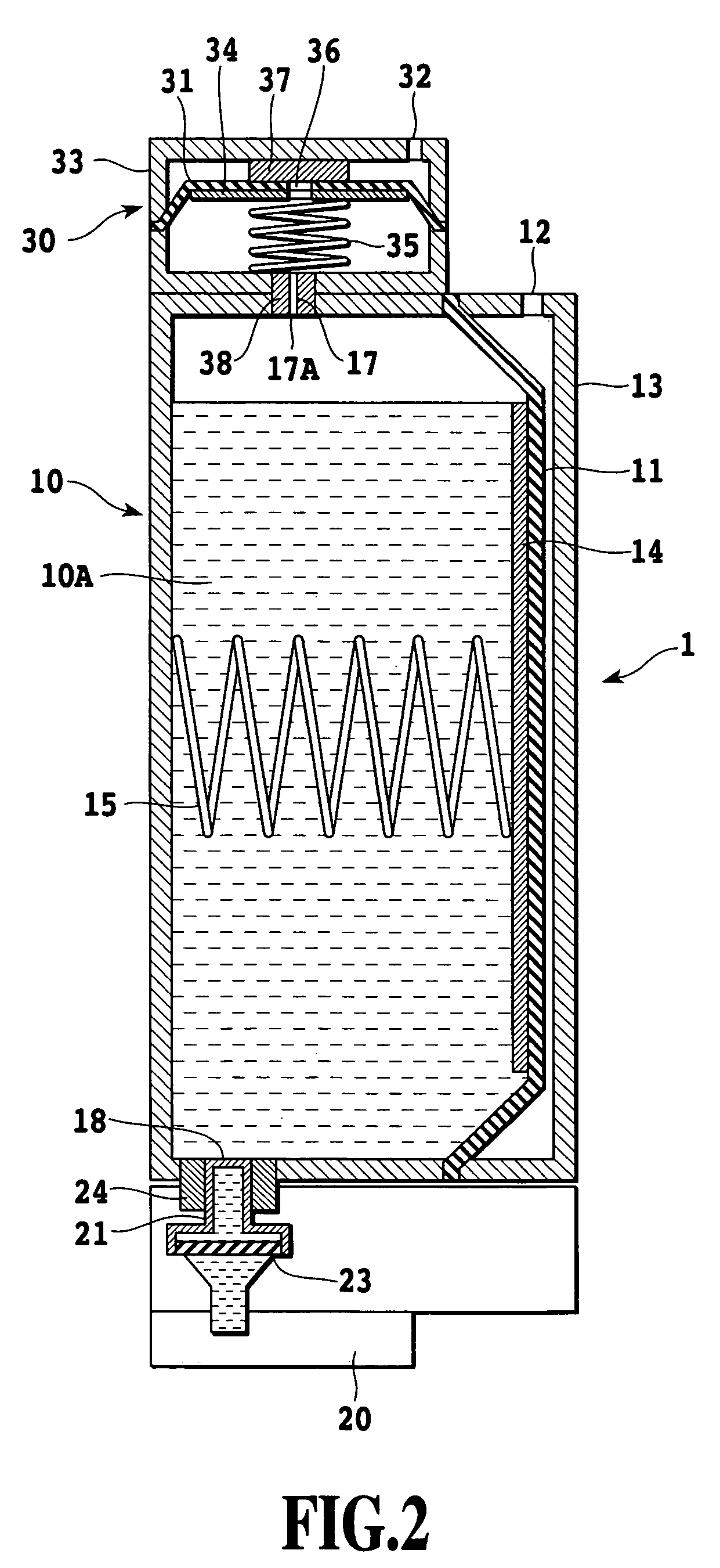
[0050]FIG. 2 shows a liquid container in another embodiment of the invention, the liquid container having an ink jet printing head 20 (hereinafter simply referred to as “printing head) integrally mounted thereto. The liquid container (hereinafter also referred to as “ink container”) is generally constituted by two chambers, i.e., an ink containing chamber 10 in which an ink containing space 10A is defined and a valve chamber 30 positioned at an upper part of the ink containing chamber in a state of use as shown in this figure, and the interiors of the two chambers are in communication with each other through an air introduction channel 17. Ink to be ejected from the printing head 20 is charged in the ink containing chamber 10 and is supplied to the printing head 20. Here, the air introduction channel 17 in the state of use is positioned at an upper part of the ink containing chamber, whereby an air supply opening 17A for discharging air is also positioned upper par...

second embodiment

(Second Embodiment)

[0072]Although the first embodiment has a configuration in which the valve chamber is located higher than the ink containing chamber in the position or orientation in use, instead of relying upon the positional relationship between those elements, the same purpose can be achieved by appropriately configuring the air introduction channel.

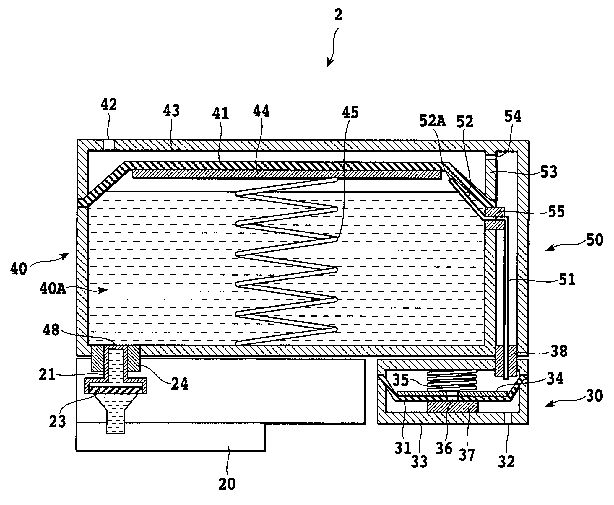
[0073]FIG. 5 shows a liquid container used in a second embodiment of the invention. A printing head 20 similar to that in the first embodiment is integrally mounted to a liquid container 2. The liquid container (hereinafter also referred to as “ink container”) is generally comprised of three chambers, i.e., an ink containing chamber 40 in which an ink containing space 40A is defined, a valve chamber 30, and an air introduction channel containing chamber 50. The interiors of the ink containing chamber 40 and the valve chamber 30 are in communication with each other through an air introduction channel 51 provided in the air introduct...

third embodiment

(Third Embodiment)

[0092]FIG. 7 shows a liquid container used in a third embodiment of the invention. In the second embodiment shown in FIG. 5, the movable member for defining the ink containing space is formed with a side section substantially in the form of an isosceles trapezoid and is supported at a peripheral section of the same. A movable member 61 of the present embodiment is shaped to have a flat continuous portion in a top surface thereof, and an end of the portion is supported by a partition wall 73 in an upper part of a container 60. Further, a part of the movable member 61 on the right side thereof in the figure is not expanded and contracted or deformed by employing a support plate 64 configured to extend toward the partition wall 73.

[0093]An air introduction channel 71 is configured such that it is in communication with the upper part of the containing space in a part thereof in the vicinity of the position where the movable member is supported, and no tube is connected...


PUM


Abstract

A liquid container has a movable member which defines a liquid containing space and which is displaced as the liquid is supplied, a valve for allowing a gas to be introduced into the containing space from the outside and for preventing the liquid from being extracted from the containing space to the outside, and an introduction channel for coupling the valve and the containing space to guide the introduced gas into the containing space. An intake port of the introduction channel located on the containing space side is positioned in an upper part of the containing space in an orientation in use. A negative pressure is kept substantially constant to consume the liquid completely. Since the air introduction for keeping the negative pressure at an adequate value is carried out in a region in a gaseous phase in the container, no leakage of ink occurs, and air is reliably introduced.

Description

[0001]This application claims priority from Japanese Patent Application No. 2002-358183 filed Dec. 10, 2002, which is incorporated hereinto by reference.BACKGROUND OF THE INVENTION[0002]1. Field of the Invention[0003]The present invention relates to a liquid container for supplying a liquid such as ink to a pen or printing head as a printing section or to a liquid using apparatus such as a printing apparatus, for example, in an efficient and stable manner, and to an ink jet printing apparatus utilizing the liquid container.[0004]2. Description of the Related Art[0005]Ink jet printing apparatuses that form an image on a printing medium by applying ink that is a liquid to the printing medium using a liquid consuming or using apparatus such as an ink jet printing head include apparatus that form an image by ejecting ink while moving a printing head relative to a printing medium and apparatus that form an image by ejecting ink while moving a printing medium relative to a fixed printing ...

Claims


Application Information

Patent Timeline
Patent Type & Authority Patents(United States)
IPC IPC(8): B41J2/175
CPCB41J2/17513B41J2/17523B41J2/17553B41J2/17556B41J2/17566
Inventor KUWABARA, NOBUYUKIISHINAGA, HIROYUKIOHASHI, TETSUYAINOUE, RYOJIOGURA, HIDEKI
Owner CANON KK
Why Eureka
Try Eureka