Thrust bearing

a technology of thrust bearings and bearings, which is applied in the direction of sliding contact bearings, crankshafts, mechanical equipment, etc., can solve the problems of reducing the performance of torque converters, the cooling effect achieved by lubricating oil introduced into the lubricating grooves b>102/b> is not sufficient, and the copper washer is not suitable for us

Inactive Publication Date: 2005-12-20
NOK CORP
View PDF24 Cites 34 Cited by
  • Summary
  • Abstract
  • Description
  • Claims
  • Application Information

AI Technical Summary

Problems solved by technology

However, since the needle bearing and the copper washer are expensive, needs for a synthetic resin thrust bearing which can be inexpensively manufactured have been increased in recent years.
However, in the conventional synthetic resin thrust bearing 100 shown in FIGS. 14A and 14B, since the lubricating oil introduced into the lubricating grooves 102 is hard to be sufficiently supplied to the lubricating surface 101, and further, since a depth d of the lubricating grooves 102 is shallow, a cooling effect achieved by the lubricating oil introduced into the lubricating grooves 102 is not sufficient.
Furthermore, because of the above insufficiency, there have been pointed out problems such that a friction with an opposing sliding member is high, a performance of the torque converter is lowered, and the specific fuel consumption is increased.

Method used


Image

  • Thrust bearing
  • Thrust bearing
  • Thrust bearing

Examples


first embodiment

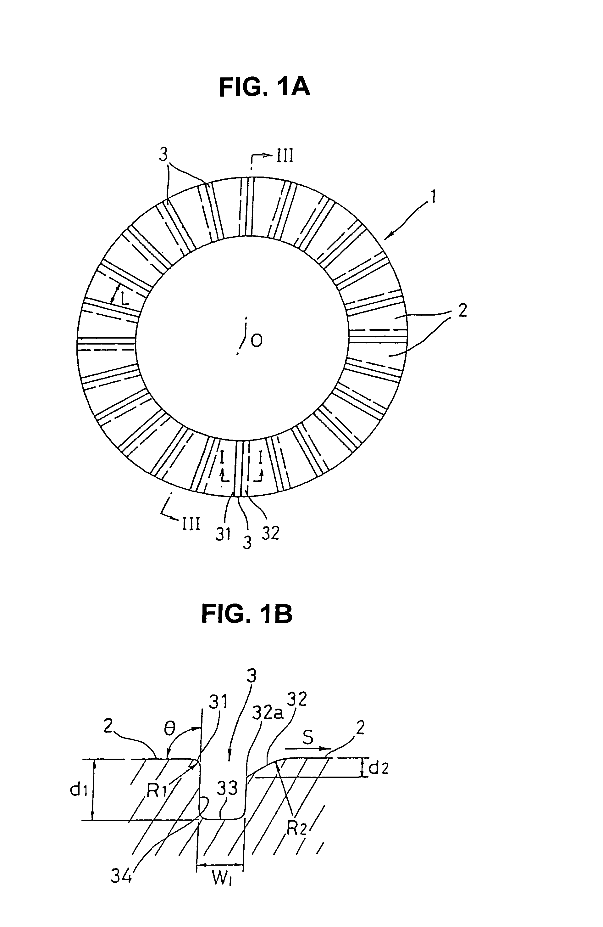
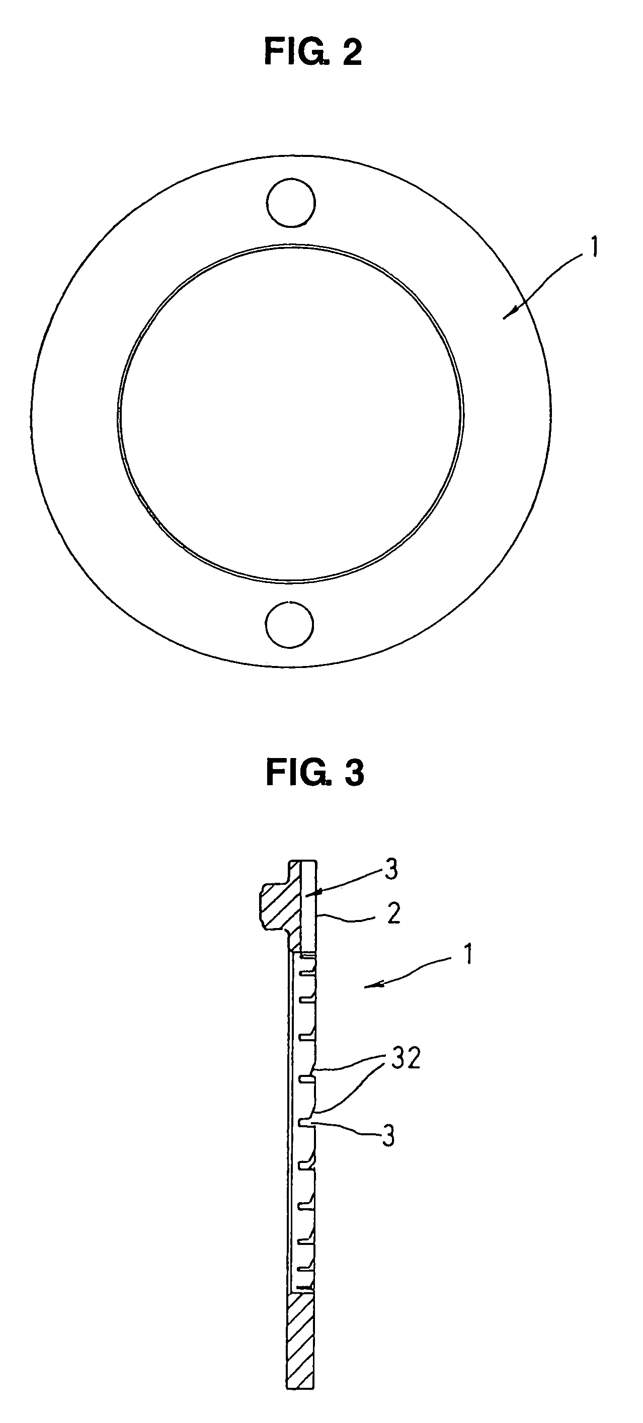
[0029]FIGS. 1A and 1B show a thrust bearing in accordance with a first embodiment, in which FIG. 1A is a front view as seen from the side of a sliding surface, and FIG. 1B is a partly enlarged cross sectional view cut along a line I—I in FIG. 1A, FIG. 2 is a back view of the same thrust bearing, and FIG. 3 is a cross sectional view cut along a line III-O-III in FIG. 1A.

[0030]A thrust bearing 1 in accordance with the present embodiment is made of a synthetic resin and formed in a flat annular shape, and is structured such as to support a thrust load of a rotation member rotating only in one direction, for example, a stator of a torque converter in an automatic transmission of a motor vehicle. The thrust bearing 1 is structured such that one end surface in the axial direction forms a sliding surface 2 with an opposing sliding member, and a lot of lubricating grooves 3 extending in the radial direction are formed on the sliding surface 2 at a predetermined interval in the circumferenti...

third embodiment

[0044]FIGS. 8A and 8B show a thrust bearing in accordance with the present invention in which FIG. 8A is a front view as seen from the side of a sliding surface. and FIG. 8B is a partly enlarged cross sectional view cut along a line VIII—VIII in FIG. 8A. The present embodiment is structured such that an angled surface 36 having a depth d2 from starting print 36a is formed in the forward side with respect to the relative rotating direction S of the opposing sliding member. Further, an opposed angled surface 35 is formed in the groove shoulder in the rearward side with respect to the relative rotating direction S of the opposing sliding member.

fourth embodiment

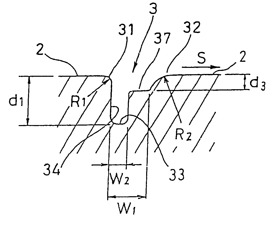
[0045]FIGS. 9A and 9B show a thrust bearing in accordance with the present invention, in which FIG. 9A is a front view as seen from the side of a sliding surface, and FIG. 9B is a partly enlarged cross sectional view cut along a line IX—IX in FIG. 9A. The present embodiment is structured such that a step portion 37 having a depth d3 is formed in the forward side with respect to the relative rotating direction S of the opposing sliding member. Further, in the same manner as that in FIGS. 1A and 1B, the first curved surface 31 having the radius R1 of curvature of 0.5 mm or less is formed in the groove shoulder in the rearward side with respect to the relative rotating direction S of the opposing sliding member, and the second curved surface 32 having the radius R2 of curvature which is substantially larger than the radius R1 is formed in the groove shoulder in the forward side. Further, a groove width W2 between the groove inner wall 34 and the step portion 37 is set to be about a hal...


PUM


Abstract

In a thrust bearing supporting a load in a thrust direction in a rotary portion, a size of a curved surface in the forward side of a lubricating groove with respect to a relative rotating direction of an opposing sliding member is set to be larger than a size of a curved surface in the rearward side of the lubricating groove with respect to the relative rotating direction, and a depth of the lubricating groove is set to be deeper than a starting point in the side of a groove bottom of the curved surface formed in the groove shoulder in the forward side of the lubricating groove with respect to the rotating direction, so that a lubricating effect and a cooling effect are increased.

Description

[0001]This is a nationalization of PCT / JP02 / 03001 filed Mar. 27, 2002 and published in Japanese.TECHNICAL FIELD[0002]The present invention relates to a thrust bearing which supports a load in the thrust direction in a rotation portion.BACKGROUND ART[0003]A stator of a torque converter in an automatic transmission of a motor vehicle can rotate only in one direction by a one-way clutch, and a thrust load applied to the stator is supported by a thrust bearing. In the thrust bearing of the torque converter, a low friction is required for the purpose of reducing a loss of power energy transmission under a high speed driving condition so as to improve a specific fuel consumption. Accordingly, as this kind of thrust bearing, there has been employed a needle bearing, or a copper washer or the like. However, since the needle bearing and the copper washer are expensive, needs for a synthetic resin thrust bearing which can be inexpensively manufactured have been increased in recent years.[0004...

Claims


Application Information

Patent Timeline
Patent Type & Authority Patents(United States)
IPC IPC(8): F16C17/04F16C33/10
CPCF16C33/1065F16C17/047F16C33/1075F16C33/20
Inventor HONDA, TADASHISEKINE, KATSUMIWATANABE, SHIGERU
Owner NOK CORP
Why Eureka
Try Eureka