Ultrasonic microtube dental instruments and methods of using same

a dental instrument and ultrasonic technology, applied in the field of dental instruments, can solve the problems of reducing the amount of tooth structure which needs to be removed to expose enough broken instruments to allow removal, and affecting the effect of root canal procedur

Inactive Publication Date: 2005-12-20
SAN DIEGO SWISS MACHINING
View PDF7 Cites 346 Cited by
  • Summary
  • Abstract
  • Description
  • Claims
  • Application Information

AI Technical Summary

Benefits of technology

[0012]Because of these and other problems in the art, disclosed herein, among other things, are ultrasonic microtube dental instruments designed to cut around a broken instrument by allowing the broken instrument to be placed within a lumen of the microtube instrument while simultaneously boring around all sides with an external cutting edge of the microtube instrument. In this way the amount of tooth structure which needs to be removed to expose enough of the broken instrument to allow removal is decreased. Further, the microtube instrument is often a stronger boring instrument.

Problems solved by technology

During root canal preparation procedures, the potential for instrument breakage is always present.
Historically, the consequences of leaving and / or bypassing broken instruments have been discussed in dental literature and can be serious.
In some cases, leaving the broken instrument in the tooth can necessitate extraction of the tooth in the future resulting in a loss of any benefit obtained from performing the root canal procedure in the first place.
Historically, retrieving broken instruments posed formidable challenges.
In particular, most broken instruments were files, drills, bores, or other cutting instruments that broke because of becoming wedged inside the structure of the tooth.
Therefore, the very fact that the instrument was broken generally indicated that the instrument had become stuck in the tooth structure and could not be easily pulled free.
Further, the instrument would often break at a point not easily visible or accessible to the clinician as a drill or similar instrument could break at a point within its own hole and therefore can not be accessed by an instrument larger than it itself without boring out additional space.
In still further situations, as structure is removed from around the broken instrument, the structure causing the wedge may be destroyed freeing the broken instrument.
As time has passed and technologies improved, retrieval techniques have evolved but are still oftentimes ineffective because of limited vision and / or restricted space.
Because of the need to access the instrument and visualize the correction, efforts directed toward instrument retrieval, even when successful, often weaken roots due to overzealous canal enlargement, which in turn predisposes them to subsequent fracture and the loss of a tooth.
Indeed, the prognosis of a tooth is seriously compromised if the efforts to remove a broken instrument lead to iatrogenic events, such as a ledged canal or root perforation.
In these situations, the tooth is again often lost and the purpose of the procedure was compromised by the broken instrument.
Because of these types of issues, the greatest challenge to removing broken instruments is to remove them safely without unnecessarily compromising the remaining tooth structure.
The problem with these methods for exposing the broken instrument is the size of the instruments and techniques employed oftentimes result in excessive loss of tooth structure during these procedures.
Further, if smaller instruments are used, there is risk that these instruments (which are much more fragile than the broken instrument was) may also break further complicating the problem.
For these reasons, it is not uncommon for iatrogenic problems to occur when attempting to retrieve a broken instrument.
In other instances, deviating from the long axis of a canal while attempting to drill around can lead to a ledge or a root perforation.

Method used


Image

  • Ultrasonic microtube dental instruments and methods of using same
  • Ultrasonic microtube dental instruments and methods of using same
  • Ultrasonic microtube dental instruments and methods of using same

Examples


first embodiment

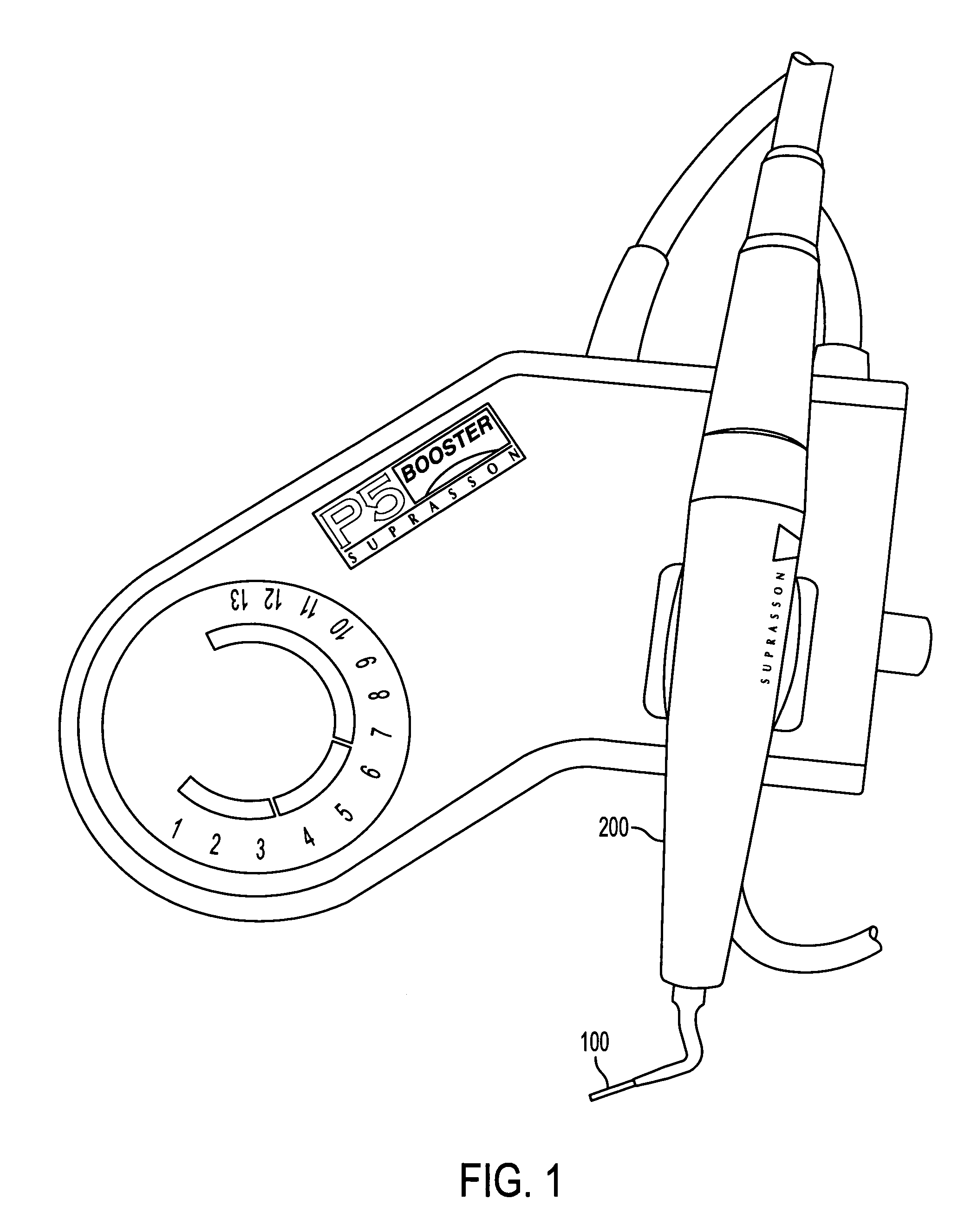
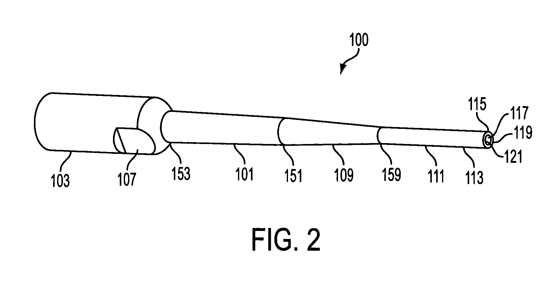
[0025]the microtube instrument (100), is illustrated in FIGS. 2–4. This is a straight microtube instrument (100). The microtube instrument (100) generally comprises an elongated shank (101), which may be of any elongated form but is preferably of generally cylindrical shape with a relatively constant diameter. Towards the proximal end (153) of the elongated shank (101) there is attached a connector (103). The connector (103) in these figures comprises an internally threaded socket (105) for threadably mounting on the end of a shaft (generally on the ultrasonic generator (200)). The connector (103) further includes at least one flat outer surface (107). In another embodiment, the entire outer surface is composed of a plurality of flat surfaces. The flat outer surface (107) provides a place for engagement by a wrench or the like for threadably tightening and loosening the microtube instrument (100) from the ultrasonic generator (200). The connector (103) may be separable from the micr...

second embodiment

[0031]FIGS. 5–6 provide for a microtube instrument (100) that provides an additional modification to the instrument shown in FIGS. 2–4. In this embodiment, the shank (101) is bent at an angle beyond the connector (103). While any type of angle maybe used it is preferred that the shank (101) be bent into a contra-angle. A contra-angle portion actually comprises two separate angles as the shank (101) is first curved or bent in a first direction away from the original axis of the shank (101), and is then bent back across the same axis. It is preferred, but by no means required, that the first bend forms an angle (505) of about 15 degrees to about 25 degrees with the original axis (503) and the second bend forms an angle (507) of about 45 degrees to about 70 degrees to the same axis (505) as shown in FIG. 5. The contra-angle will generally occur prior to the intermediate section (109), if one is present, but that is also not required.

[0032]The various embodiments of instruments shown in...


PUM


Abstract

Systems and methods related to ultrasonic microtube dental instruments designed to cut around a broken instrument by allowing the broken instrument to be placed within a lumen of the microtube instrument while simultaneously boring with the broken instrument and being guided by the broken instrument.

Description

CROSS REFERENCE TO RELATED APPLICATIONS[0001]This application claims priority to U.S. Provisional Patent Application Ser. No. 60 / 372,332 filed Apr. 12, 2002 the entire disclosure of which is herein incorporated by reference.BACKGROUND[0002]1. Field of the Invention[0003]This disclosure relates to the field of dental instruments. In particular, to ultrasonic microtube dental instruments designed to remove the remnants of broken instruments from teeth.[0004]2. Brief Description of the Related Art[0005]During root canal preparation procedures, the potential for instrument breakage is always present. When an instrument breaks during the procedure, the clinician is generally left with two options, attempt to remove the broken instrument, or leave the broken instrument in place and bypass the broken instrument while continuing the procedure.[0006]Historically, the consequences of leaving and / or bypassing broken instruments have been discussed in dental literature and can be serious. In so...

Claims


Application Information

Patent Timeline
Patent Type & Authority Patents(United States)
IPC IPC(8): A61C1/07A61C3/03A61C5/02
CPCA61C1/07A61C5/026A61C3/03A61C17/20A61C5/46
Inventor HICKOK, TERESARUDDLE, CLIFFORD
Owner SAN DIEGO SWISS MACHINING
Why Eureka
Try Eureka