Electrodeless self-ballasted fluorescent lamp and discharge lamp operating device

a fluorescent lamp and self-balancing technology, which is applied in the direction of electric variable regulation, process and machine control, instruments, etc., can solve the problems of difficult to implement a dimmable fluorescent lamp, electrodeless self-balancing fluorescent lamps which have not yet developed, and the inability to carry out smooth dimming

Inactive Publication Date: 2005-12-20
PANASONIC CORP
View PDF13 Cites 36 Cited by
  • Summary
  • Abstract
  • Description
  • Claims
  • Application Information

AI Technical Summary

Benefits of technology

[0014]In one preferred embodiment, the dimming controller has a sawtooth wave generator including a differentiating circuit that includes a capacitor and a resistor, the differentiating circuit is connected to a collector terminal of a transistor for generating a pulse wave synchronized with the turn-on and turn-off of the phase-controlled AC voltage, an output terminal of the differentiating circuit is connected with an anode of a diode wh

Problems solved by technology

On the other hand, since a fluorescent lamp emits light by discharge, it is difficult to implement a dimmable fluorescent lamp that can be practically used by merely adjusting electric power supplied thereto like an incandescent lamp.
However, the fact is that an electrodeless self-ballasted fluorescent lamp which is dimmable has not yet developed.
Therefore, if deeper dimming is carried out using a fluorescent lamp having electrodes, extinguishing occurs at the instant when a dimming volta

Method used


Image

  • Electrodeless self-ballasted fluorescent lamp and discharge lamp operating device
  • Electrodeless self-ballasted fluorescent lamp and discharge lamp operating device
  • Electrodeless self-ballasted fluorescent lamp and discharge lamp operating device

Examples


embodiment 1

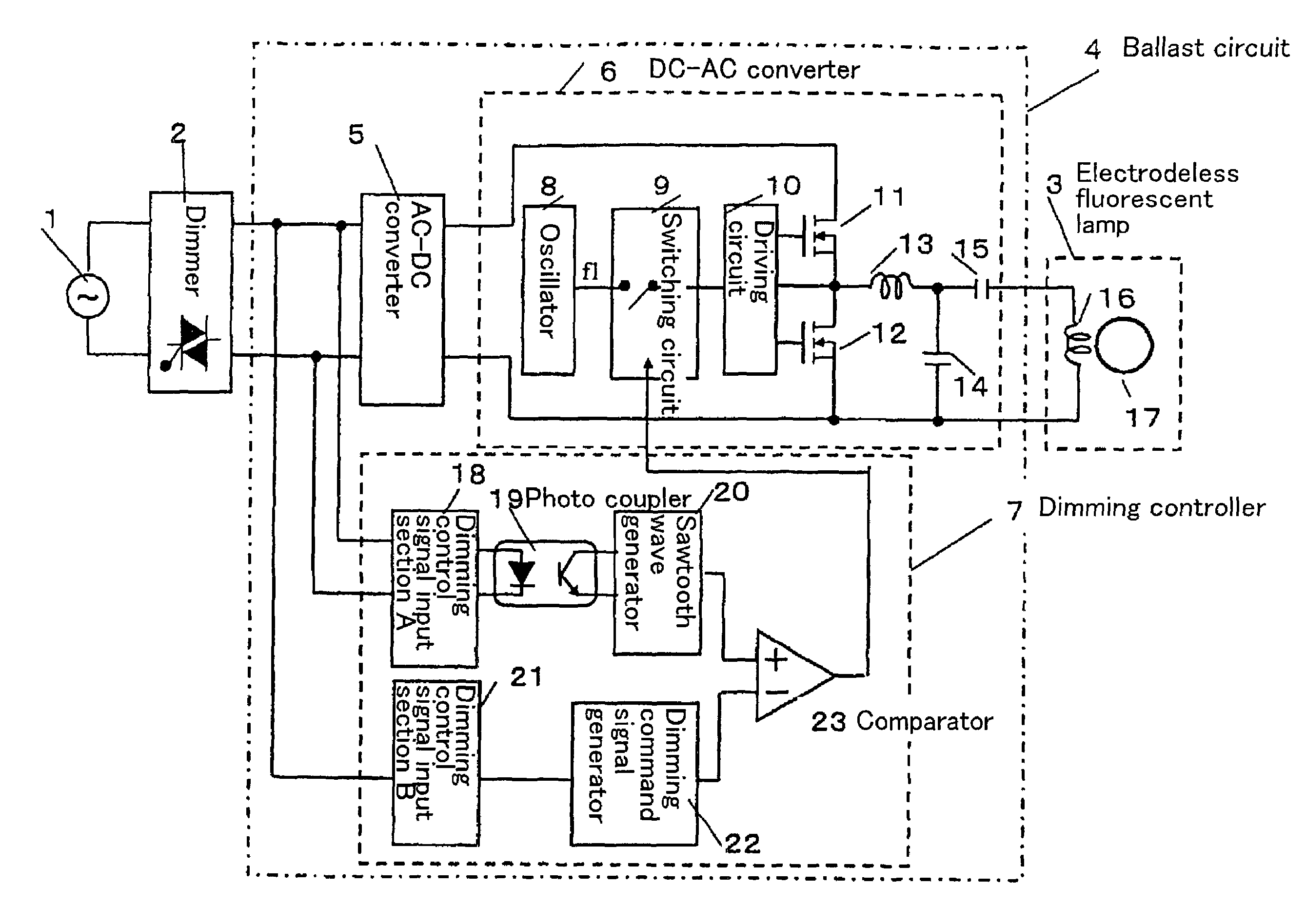
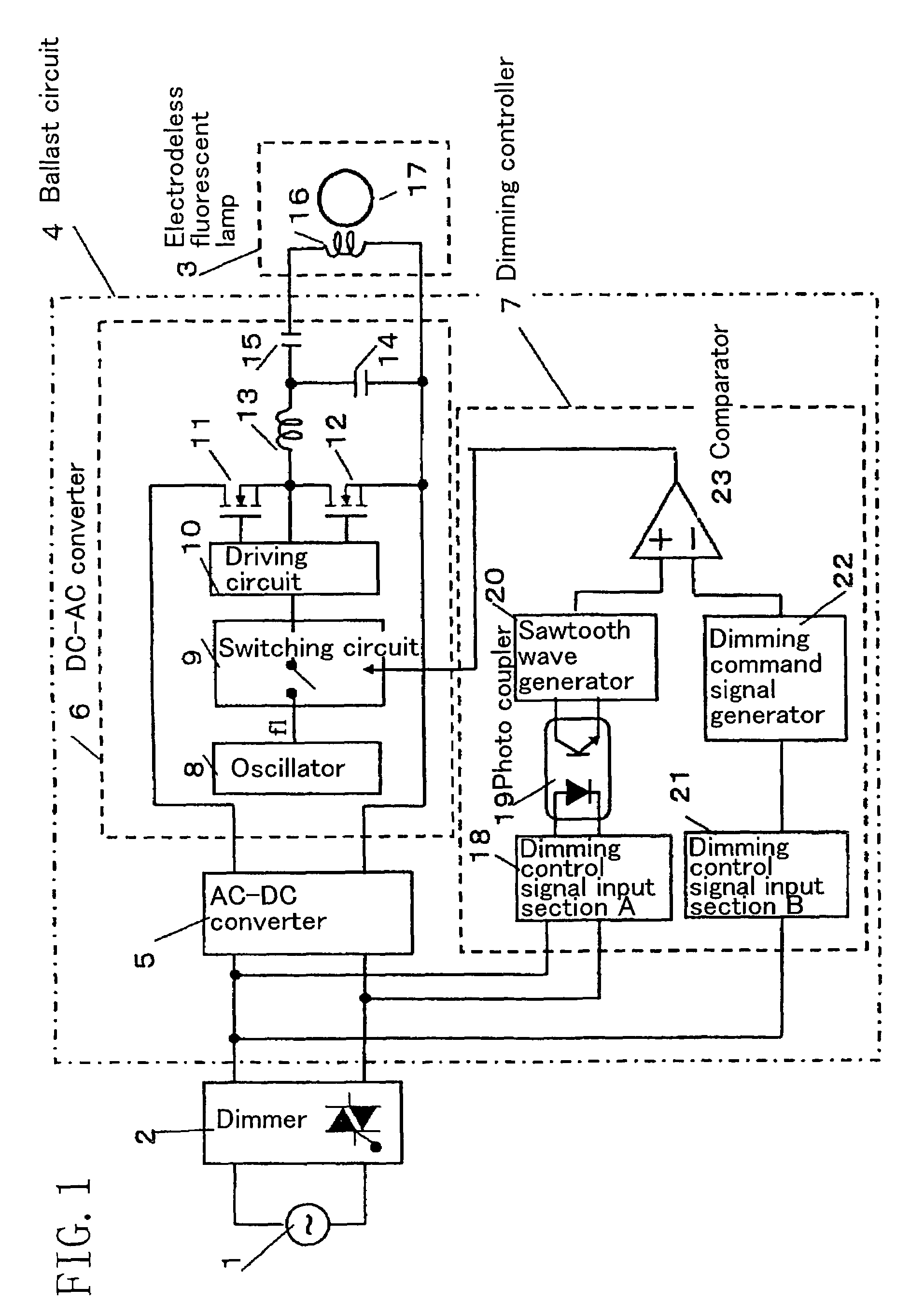
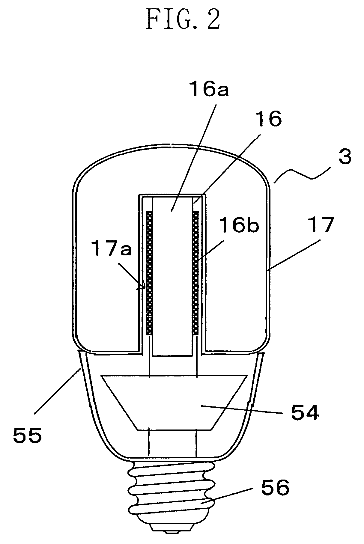
[0029]FIG. 1 schematically shows the configuration of a discharge lamp operating device according to a first embodiment of the present invention. And FIG. 2 is a cross-sectional view of the discharge lamp operating device of the present embodiment implemented as an electrodeless self-ballasted fluorescent lamp.

[0030]The electrodeless self-ballasted fluorescent lamp of the present embodiment includes: an electrodeless fluorescent lamp 3; a ballast circuit 4 (circuit board 54) for applying a high-frequency voltage to the electrodeless fluorescent lamp 3; and a lamp base 56 electrically connected to the ballast circuit 4 (circuit board 54). The circuit board 54 shown in FIG. 2 is formed with the ballast circuit 4 shown in FIG. 1. Specifically, the circuit board 54 is formed with wirings provided as shown in the ballast circuit 4, and is attached with respective circuit components.

[0031]As shown in FIG. 2, in the electrodeless self-ballasted fluorescent lamp, the electrodeless fluoresce...

embodiment 2

[0068]Hereinafter, a second embodiment of the present invention will be described with reference to FIG. 5. Although the configuration of a discharge lamp operating device of the present embodiment is similar to that described in the first embodiment, a sawtooth wave generator 20 for detecting the turn-on of a phase-controlled voltage is formed differently from the counterpart in the first embodiment, and can be formed inexpensively without using any IC in the configuration of the present embodiment.

[0069]FIG. 5 shows a circuit for detecting the turn-on of a phase-controlled voltage in the present embodiment, and in particular shows the configuration of the sawtooth wave generator 20. It should be noted that the same constituting elements as the counterparts described in the first embodiment are identified by the same reference characters, and the further description thereof will be omitted.

[0070]The sawtooth wave generator 20 shown in FIG. 5 has: a differentiating circuit 201; a di...


PUM


Abstract

An electrodeless self-ballasted fluorescent lamp includes an electrodeless fluorescent lamp 3, a ballast circuit 4 and a lamp base which are formed as one unit. The ballast circuit 4 includes: an AC-DC converter 5; a DC-AC converter 6 formed so as to intermittently drive the electrodeless fluorescent lamp 3; and a dimming controller 7 formed so as to detect the turn-on of a phase-controlled AC voltage and output an intermittent command signal for changing the ratio between an operating period and an extinguishing period to the DC-AC converter 6. Furthermore, the dimming controller 7 is formed so as to output a signal for extinguishing the electrodeless fluorescent lamp 3 before the operation thereof becomes unstable.

Description

CROSS-REFERENCE TO RELATED APPLICATIONS[0001]This application is a National Stage of International Application No. PCT / JP03 / 07234, filed Jun. 6, 2003. This application claims the benefit of JP 2002-167580, filed Jun. 7, 2002. The disclosures of the above applications is incorporated herein by reference.TECHNICAL FIELD[0002]The present invention relates to discharge lamp operating devices. In particular, the present invention relates to electrodeless self-ballasted fluorescent lamps in which electrodeless fluorescent lamps can be dimmed.BACKGROUND ART[0003]A fluorescent lamp has been widely used from global environmental protection and economic standpoints because it has a higher degree of efficiency and a longer life as compared with an incandescent lamp. In recent years, as an economical light source, an electrodeless self-ballasted fluorescent lamp having no electrode has been attracting much attention since its life is several times longer than that of a conventional self-ballast...

Claims


Application Information

Patent Timeline
IPC IPC(8): H05B41/28H05B41/285H05B41/392
CPCH05B41/2806H05B41/2813H05B41/2853H05B41/3921H05B41/3924H05B41/3927Y02B20/185Y02B20/186Y02B20/22Y10S315/04Y02B20/00
Inventor MATSUBAYASHI, YOKOTAKAHASHI, KENICHIROMIYAZAKI, KOUJIKOMINAMI, SATOSHIKURACHI, TOSHIAKITAKEDA, MAMORU
Owner PANASONIC CORP
Why Eureka
Try Eureka