Unlock instant, AI-driven research and patent intelligence for your innovation.

Vehicular alternator failure determination apparatus using commutating device voltage

a technology of commutating device and failure determination apparatus, which is applied in the direction of electric generator control, dynamo-electric converter control, instruments, etc., can solve the problems of difficult to distinguish the ripple components clearly, the failure of the vehicle alternator to always perform power generation, and the difficulty of obtaining an accurate average or mean value upon calculation of average or mean output voltage, etc., to achieve accurate results

Inactive Publication Date: 2005-12-20
MITSUBISHI ELECTRIC CORP
View PDF40 Cites 0 Cited by
  • Summary
  • Abstract
  • Description
  • Claims
  • Application Information

AI Technical Summary

Benefits of technology

The present invention provides a vehicular alternator failure determination apparatus that can accurately detect alternator failures. The apparatus uses a difference voltage between maximum and minimum voltages of the alternator commutating device to determine if the alternator is in a failure state. The apparatus can also calculate the average voltage and detect ripple voltages to estimate the location of failure. This invention helps to improve the accuracy and reliability of detecting alternator failures.

Problems solved by technology

However, the vehicular alternator does not always perform power generation but irregular intermittent power generation.
Moreover, since the influence of noise on the ripple component is also large, there is a problem that it is difficult to make a clear distinction between the ripple component due to an engine operating condition change and the ripple voltage resulting from noise or failure.
Furthermore, since the output voltage of the vehicular alternator is varying in accordance with time for the reasons as stated above, there is also another problem that it is difficult to obtain an accurate average or mean value upon calculation of an average or mean output voltage of the alternator.

Method used


Image

  • Vehicular alternator failure determination apparatus using commutating device voltage
  • Vehicular alternator failure determination apparatus using commutating device voltage
  • Vehicular alternator failure determination apparatus using commutating device voltage

Examples


embodiment 1

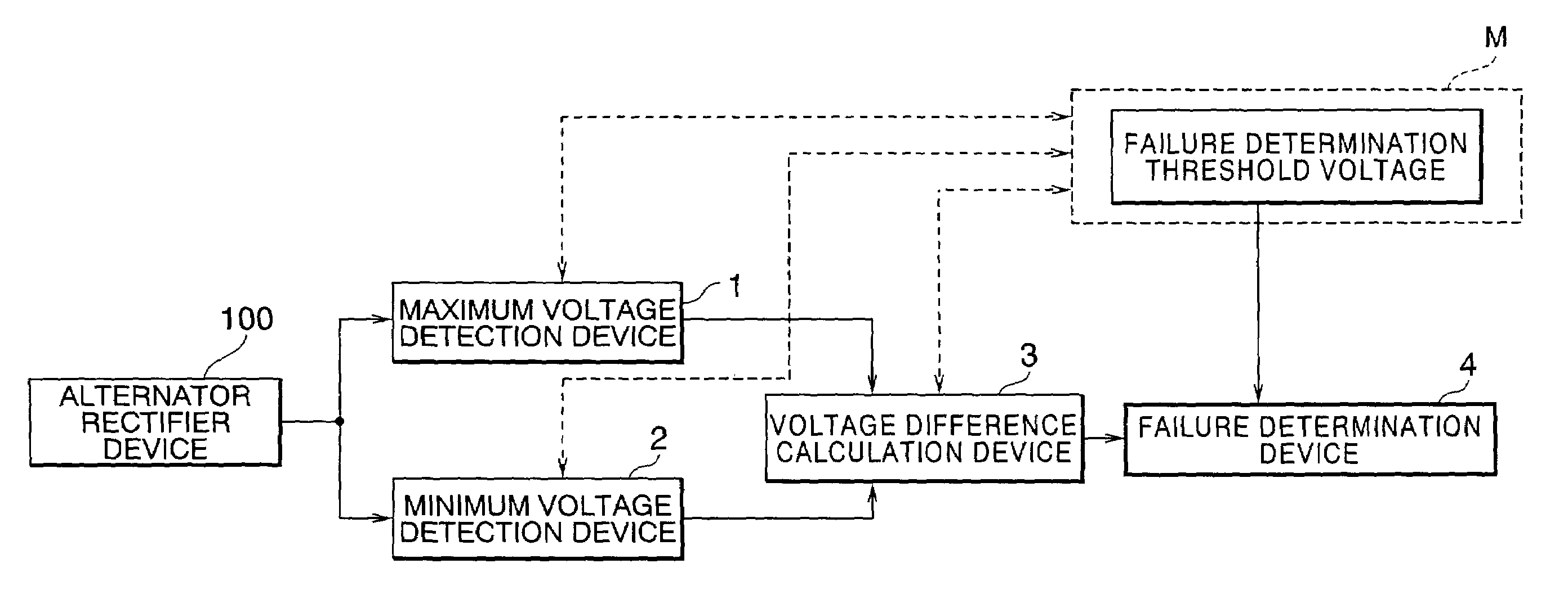
[0028]FIG. 1 is a block diagram that shows the configuration of a vehicular alternator failure determination apparatus according to a first embodiment of the present invention. When there is a failure in a commutator element or a stator coil of a vehicular alternator, the waveform of an output voltage of an alternator rectifier or commutating device 100 comes to include a ripple voltage waveform larger than that during normal operation thereof. FIGS. 2(a) through 2(e) show the waveforms of the output voltage of the alternator commutating device 100 at the times of normal operation and failure thereof. FIG. 2(a) shows the case where the alternator is in the state of normal power generation. FIG. 2(b) shows the case where one commutator element is in the state of an open-circuit failure. FIG. 2(c) shows the case where two commutator elements are in the state of an open-circuit failure. FIG. 2(d) shows the case where one commutator element is in the state of a short-circuit failure. FI...

embodiment 2

[0034]FIG. 4 is a block diagram that shows the configuration of a vehicular alternator failure determination apparatus according to a second embodiment of the present invention. In this embodiment, similar to the above-mentioned first embodiment, a determination of failure of a vehicular alternator is made by utilizing the fact that when there is a failure in a commutator element or a stator coil of the vehicular alternator, the waveform of an output voltage of a rectifier or commutating device comes to include a ripple voltage waveform larger than that during normal operation thereof, as shown in FIGS. 2(a) through 2(e).

[0035]In FIG. 4, a reference symbol A designates a constant cycle operation function that operates respective devices 5 through 8 at a prescribed cycle or period, that is, provides a synchronization signal to the respective devices 5 through 8 so as to make them operate at the constant cycle or period, if they are hardware, as shown in the following embodiments for ...

embodiment 3

[0039]FIG. 6 is a block diagram that shows the configuration of a vehicular alternator failure determination apparatus according to a third embodiment of the present invention. In this embodiment, a determination of failure of a vehicular alternator is made by utilizing the fact that when there is a failure in a commutator element or a stator coil of the vehicular alternator, the waveform of an output voltage of a rectifier or commutating device comes to include a ripple voltage waveform larger than that during normal operation thereof, as shown in FIGS. 2(a) through 2(e). An operation cycle changing device 9 changes the operation cycle of the vehicular alternator failure determination apparatus in accordance with the operating condition of a vehicle or the operating condition of the vehicular alternator.

[0040]In FIG. 6, the operation cycle changing device 9 detects the number of revolutions per minute of the vehicular alternator as the operating condition of the vehicle by means of...


PUM


Abstract

A vehicular alternator failure determination apparatus is capable of making a failure determination accurately. The apparatus includes a maximum voltage detection part (1) for detecting a maximum voltage of an alternator commutating device which commutates an AC output of the alternator driven by an engine, a minimum voltage detection part (2) for detecting a minimum voltage of the alternator commutating device, a voltage difference calculation part (3) for detecting a difference voltage from outputs of the maximum and minimum voltage detection parts, and a failure determination part (4) which determines that the alternator is in a failure state, when an output of the voltage difference calculation part is equal to or greater than a prescribed voltage.

Description

BACKGROUND OF THE INVENTION[0001]1. Field of the Invention[0002]The present invention relates to a vehicular alternator failure determination apparatus, and more particularly, to the decision of failure determination conditions upon making a failure determination of a vehicular alternator.[0003]2. Description of the Related Art[0004]In diagnosis apparatuses for motor vehicles with known vehicular alternator failure determination means, the generation cycle or period of a ripple voltage in the output of a vehicular alternator rectifier or commutating device is measured so that a failure in a stator coil and commutator elements in the rectifier or commutating device is detected according to a variation in the ripple voltage generation cycle. Explaining this step by step, in a first step, the cycle or period of a ripple voltage waveform at a certain point in time is read in, and when the cycle thus read in is larger than zero or a predetermined value α, it is determined that the stator...

Claims


Application Information

Patent Timeline
Patent Type & Authority Patents(United States)
IPC IPC(8): G01R31/36G01R31/34H02P9/30
CPCG01R31/343
Inventor FUJIOKA, HIROSHIMATSUNAGA, TAKANORIMAEDA, TAKASHIMATSUI, TOSHINORI
Owner MITSUBISHI ELECTRIC CORP