Frame and image display device

Inactive Publication Date: 2005-12-20
IBM CORP
View PDF12 Cites 31 Cited by
  • Summary
  • Abstract
  • Description
  • Claims
  • Application Information

AI Technical Summary

Benefits of technology

[0016]In view of the foregoing background, an object of the present invention is to provide a frame capable of realizing low cost and additionally capab

Problems solved by technology

Consequently, when the liquid crystal display panel 33 is pressed by the upper frame 30 ha

Method used


Image

  • Frame and image display device
  • Frame and image display device
  • Frame and image display device

Examples


Example

First Embodiment

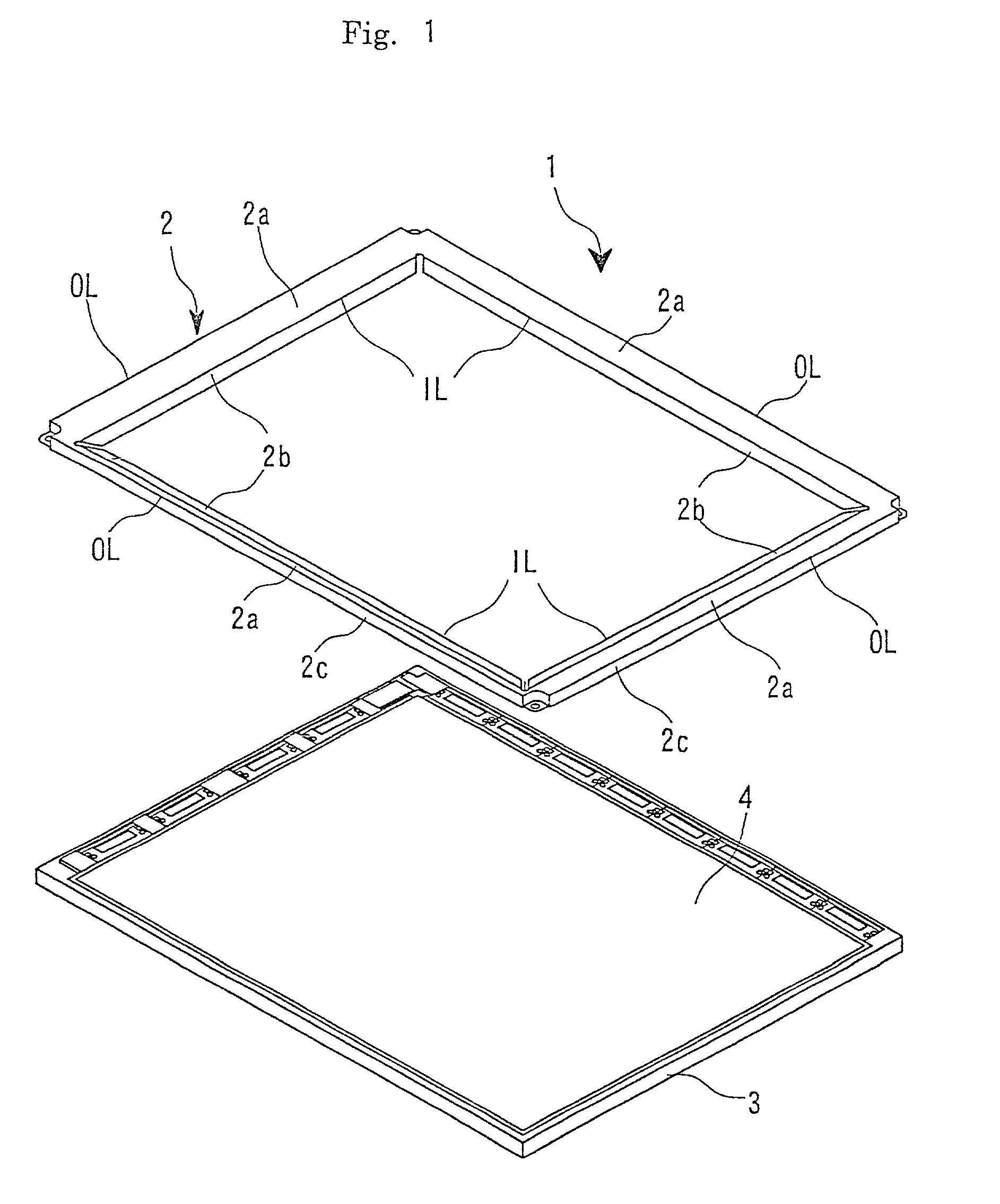
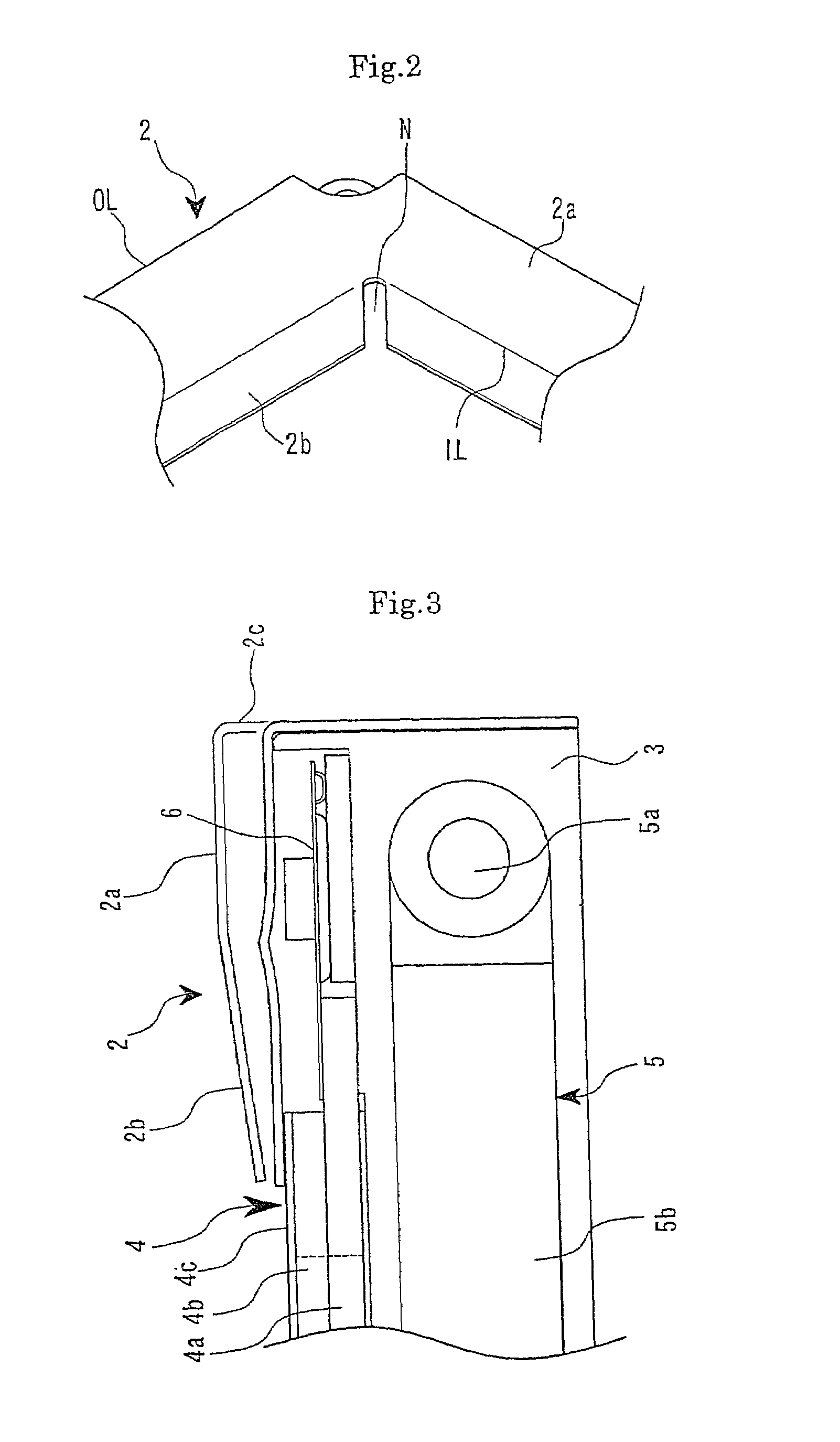
[0044]FIGS. 1 to 3 show a liquid crystal display 1 of a first embodiment. FIG. 1 is an exploded perspective view of the liquid crystal display 1. FIG. 2 is a partly enlarged view of FIG. 1. FIG. 3 is a fragmentary sectional view of FIG. 1.

[0045]As shown in FIGS. 1 to 3, the liquid crystal display 1 comprises an upper frame 2 and a lower frame 3. A liquid crystal display panel 4, a backlight unit 5 and a TAB (Tape Automated Bonding) 6 are contained within the lower frame 3 made of resin.

[0046]The upper frame 2 is constituted of a press-molded part made of stainless steel and forms a display window delimiting an image display region of the liquid crystal display panel 4. It is a current mainstream that a thickness of the stainless steel to be used is about 0.3 mm. Aluminum alloy is sometimes used as a material of the upper frame 2. The aluminum alloy having a lower specific gravity than that of the stainless steel is particularly suitable for weight saving.

[0047]The li...

Example

Second Embodiment

[0058]A second embodiment of the present invention will be described below with reference to FIG. 4. FIG. 4 is a fragmentary sectional view of a liquid crystal display of the second embodiment. Note that, the same components as those of the first embodiment will be indicated by the same reference numerals, and the description thereof will be omitted.

[0059]As shown in FIG. 4, a basic constitution of the second embodiment is the same as that of the first embodiment, and a difference lies in a detailed structure of an upper frame 12.

[0060]Referring to FIG. 3 showing the first embodiment, a boundary portion between the base part 2a and the end part 2b of the upper frame 2 mounted to the liquid crystal display 1 has an upward convex protrusion, because the end part 2b is bent relative to the base part 2a in a state in which the upper frame 2 does not press the liquid crystal display panel 4. The portion of protrusion does no harm to the pressing and holding of the liquid...

Example

Third Embodiment

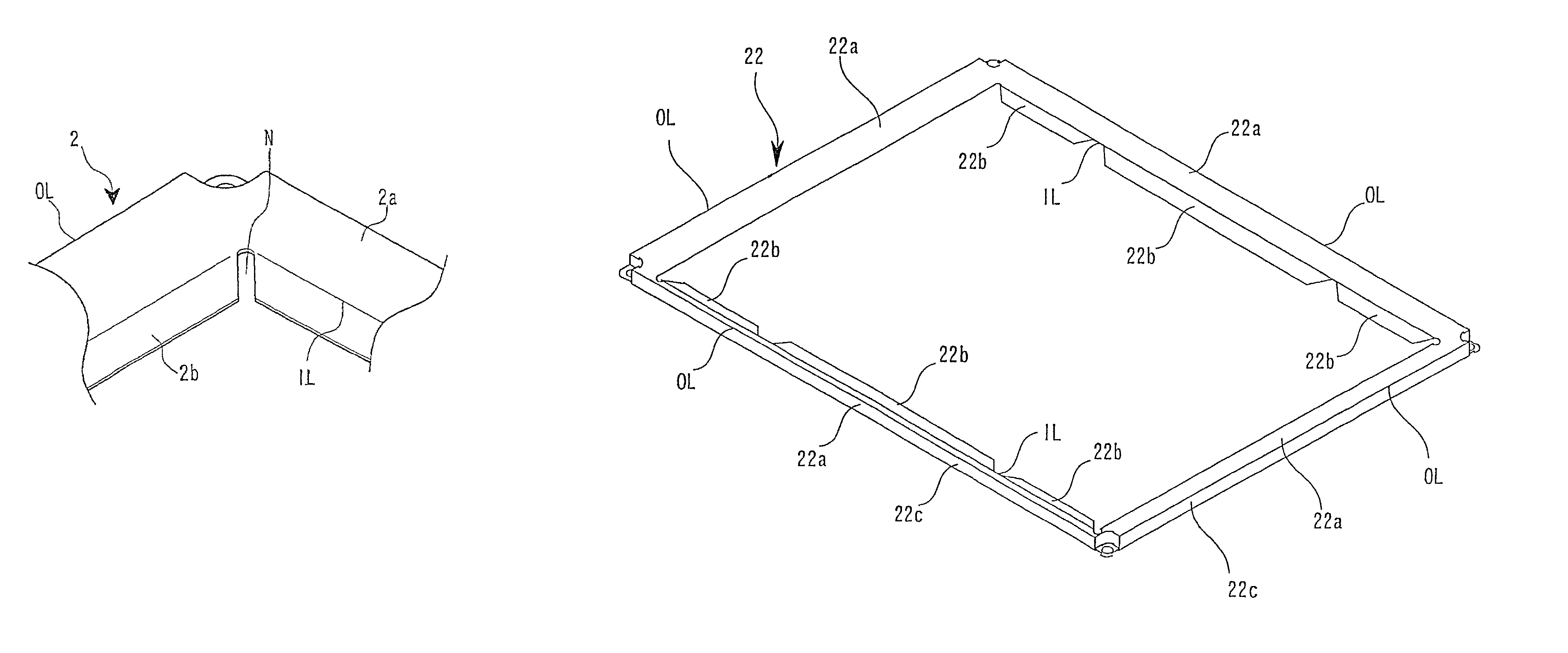
[0062]A third embodiment of the present invention will be described below with reference to FIG. 5. FIG. 5 is a perspective view of an upper frame 22 of the third embodiment.

[0063]A basic constitution of the upper frame 22 of the third embodiment is the same as that of the upper frame 2 of the first embodiment. That is, the upper frame 22 comprises a base part 22a, end parts (bent parts) 22b and side walls 22c. The base part 22a has a shape of a picture-frame continuous in the circumferential direction and has four inner limbs IL. However, the end parts 22b extend from only the inner limbs IL corresponding to longer sides of the upper frame 22, and the end parts 22b are not provided on the inner limbs IL corresponding to shorter sides of the upper frame22. Moreover, the upper frame 22 of the third embodiment is different from the upper frame 2 (12) of the first (second) embodiment in that, although the end parts 2b(12b) of the upper frame 2 (12) each have a length su...


PUM


Abstract

An upper frame comprises a base part, end parts and side walls. The base part has a picture-frame shape continuous in the circumferential direction. The base part has four inner limbs, and the end parts extend from the inner limbs. In a state in which the end parts do not press a liquid crystal display panel, the end parts are bent relative to the base part in the direction of the liquid crystal display panel which is to be placed, i.e., in the direction in which the liquid crystal display panel is to be pressed. Considering the relation to the side walls, each of the end parts forms an acute angle. The side walls are pendent from outer limbs of the base part at a substantially right angle and are continuous in the circumferential direction.

Description

BACKGROUND OF THE INVENTION[0001]1. Technical Field[0002]The present invention relates to a frame for holding a display panel such as a liquid crystal display panel and an image display device using the frame.[0003]2. Discussion of Related Art[0004]A liquid crystal display has become remarkably[0005]widespread as an image display device for a personal computer (PC) or other various types of monitors. Generally, this type of liquid crystal display comprises a backlight, which is a planar light source for lighting, placed on the back of a liquid crystal display panel, and thus the liquid crystal display is configured so as to make an image formed on a liquid crystal surface into a visible image by illuminating the overall liquid crystal surface having a predetermined dimension in uniform brightness emitted from the backlight.[0006]In the liquid crystal display, the liquid crystal display panel having a liquid crystal material sealed between a pair of glass substrates is sandwiched and...

Claims


Application Information

Patent Timeline
IPC IPC(8): G02F1/13G02F1/1333G02F1/133G09F9/00
CPCG02F1/133308G02F1/133325G02F1/133
Inventor NATSUYAMA, YOSHIFUMI
Owner IBM CORP
Why Eureka
Try Eureka