Video pose tracking system and method

a tracking system and video pose technology, applied in the field of video pose tracking system and method, can solve the problems of insufficient color or intensity contrast between each target, the inability of many operating environments to guarantee static reference background illumination, and the difficulty of current optical tracking system in distinguishing between the markers and the scene background

Active Publication Date: 2005-12-20
CLARONAV
View PDF23 Cites 126 Cited by
  • Summary
  • Abstract
  • Description
  • Claims
  • Application Information

AI Technical Summary

Problems solved by technology

Current optical tracking systems can have difficulties in distinguishing between the markers and the scene background due to inadequate illumination of the markers.
However, the marker shapes can have a widely varying appearance in video images under different lighting conditions, and therefore a static reference background illumination cannot be guaranteed in many operating environments.
A further disadvantage is that a sufficient color or intensity contrast may not always be present between each target and its background.

Method used


Image

  • Video pose tracking system and method
  • Video pose tracking system and method
  • Video pose tracking system and method

Examples


Embodiment Construction

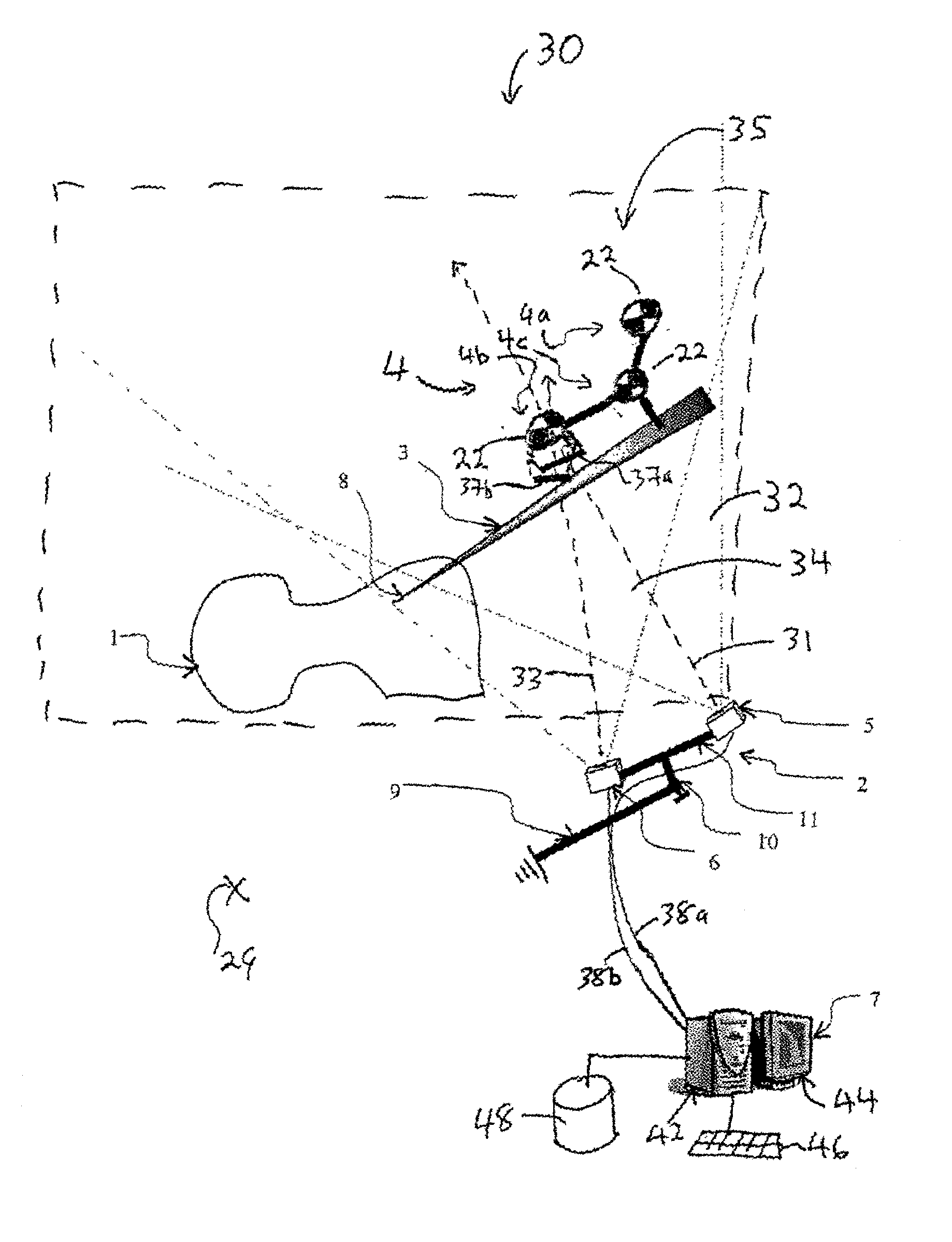
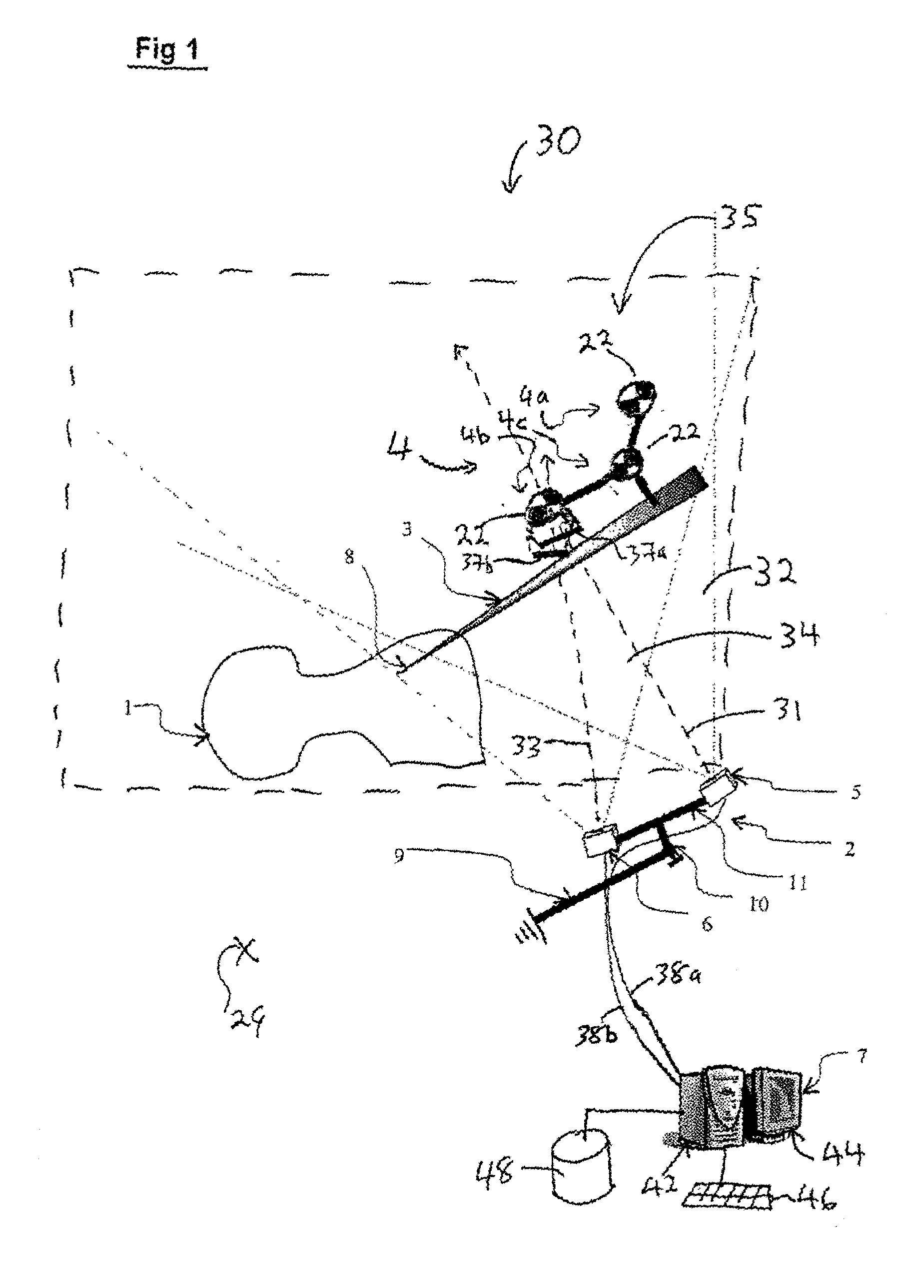
[0026]Referring to FIG. 1, a tracking system 30 has an optical sensor assembly 2 used to track the relative position and orientation (pose) of marker 4 attached to an object, such as but not limited to a surgical tool 3 tracked in relation to a portion of a patient's anatomy 1 in a surgical scene 35. The sensor assembly 2 can be a stereo sensor having a first digital video camera sensor 5 with a first field of view 32 and a second digital video camera sensor 6 with a second partially overlapping field of view 34. More than two cameras 5,6 could also be used if desired. Suitable sensors for this purpose are commercially available including, for example, the Mega-D family of stereo digital cameras sold by Videre Design (www.videredesign.com). Such cameras are typically delivered pre-calibrated to allow the association of a pixel position in each of the images with a corresponding linear ray equation in a common sensor 3D space. Otherwise, such calibration may be performed using known ...


PUM


Abstract

A measurement system and method for detecting and tracking the pose of an object displaceable in a coordinate reference frame. In the system and method a visible target pattern is provided on the object. The visible target pattern includes a series of contrast regions for providing at least two feature points. Each of these feature points is located at a juncture of an optically detectable plurality of edges. Each edge in the optically detectable plurality of edges separates different contrast regions. The method and system determine the location of the feature points by first locating the edges using the change in contrast between contrast regions, and then determining junctures of multiple edges. The method and system also involve a stereoscopic digital camera for generating a pair of digital images of the target pattern and a marker template comprising a set of reference characteristics including a relationship between the feature points.

Description

[0001]The present invention relates to the computerized optical measurement of the position and orientation of objects in space.BACKGROUND OF THE INVENTION[0002]There is a great interest in surgical and other arenas to provide for the real-time computerized measurement of a spatial position and orientation (pose) of specially marked objects moving unpredictably through an unstructured scene. For one example application, the scene may be an operating room in which surgery is performed, and the tracked objects are surgical instruments, and implants to be secured to the patient's anatomy in pre-planned positions. The pose of the surgical instruments is monitored by position sensors, such that the real-time location of the instruments can be displayed on previously acquired patient image data. The pose of the patient is also typically tracked separately, to allow for sensing of anatomy movement relative to the tracked instruments during the operation. In another example application, the...

Claims


Application Information

Patent Timeline
Patent Type & Authority Patents(United States)
IPC IPC(8): A61B19/00G06T7/00G06T7/20
CPCA61B19/5244G06K9/3216G06T7/0044G06T7/20A61B19/50A61B2019/5265A61B2019/5287A61B2019/5289A61B2019/5483G06K2009/3225A61B2090/3983A61B2090/363A61B34/20A61B2090/364A61B34/10A61B2034/2065G06T7/74G01B11/002G01B11/26G06V10/245
Inventor DEKEL, DORONGATTI, CLAUDIO
Owner CLARONAV
Why Eureka
Try Eureka