Sliding screen door

a sliding screen and door technology, applied in the field of sliding screen doors, can solve the problems of reducing the ability to block insects, reducing the operating force of the movable edge member, and the disadvantageous limitation of certain types of materials, so as to prevent separation, reduce the force of buffering the operating force of the movable edge member, and facilitate the manufacture at low cost

Inactive Publication Date: 2005-12-27
SEIKI JUKO
View PDF11 Cites 37 Cited by
  • Summary
  • Abstract
  • Description
  • Claims
  • Application Information

AI Technical Summary

Benefits of technology

[0006]An object of the present invention is to provide a sliding screen door having a net guide that moves in association with an opening and closing movement of a net, wherein the opening and closing operation of the screen door can be performed smoothly while providing a buffering effect with an adequate resistance, without hindering the opening and closing operability of the movable edge member, by enabling a reaction force of the net guide, which is generated when it bends, to be used as a force for buffering the operating force of the movable edge member, the net guide being formed by connecting guide pieces formed of a suitable resin.
[0007]Another object of the present invention is to provide a sliding screen door having an improved insect blocking effect by eliminating notches that have been required in conventional sliding screen doors by allowing the bottom portion of the net guide, which is formed of extruded material, to bent, thus achieving the net guide to bent without forming spaces between adjacent guide pieces.
[0008]Still another object of the present invention is to enable production of the aforementioned net guide, as well as a sliding screen door having the same, easily and as cheaply as possible.

Problems solved by technology

However, it is necessary to use a resin having a sufficient durability against repeated bending and having an adequate resistance against bending as the material forming the aforementioned net guide, and thus the material is disadvantageously limited to certain types.
Therefore, those notches form spaces, and of course increasing the size of those notches may lead to a reduced ability to block insects.
In the case of this type of net guide, it is troublesome to connect of each rigid unit, and in addition, a force for buffering the operating force of the movable edge member as in the case of the aforementioned net guide using extruded thermoplastic synthetic resin, cannot be generated.

Method used


Image

  • Sliding screen door
  • Sliding screen door
  • Sliding screen door

Examples


first embodiment

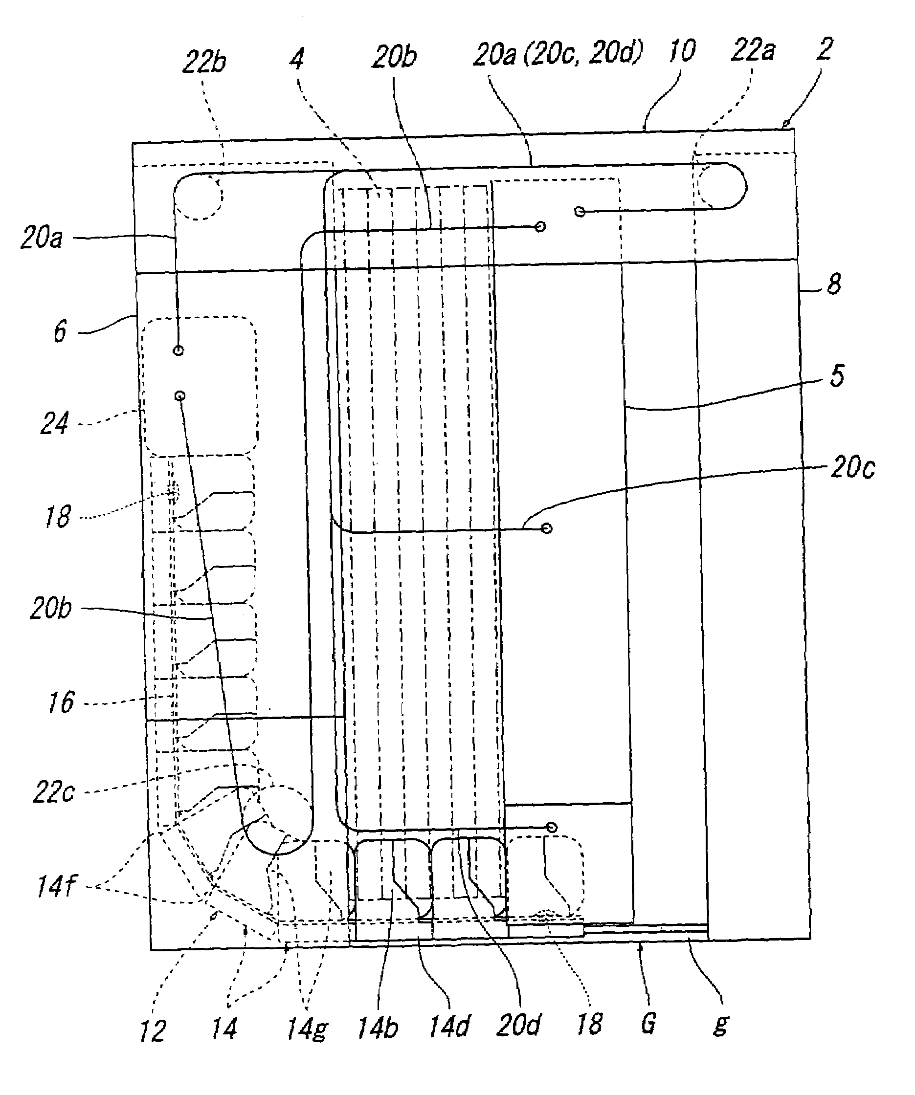
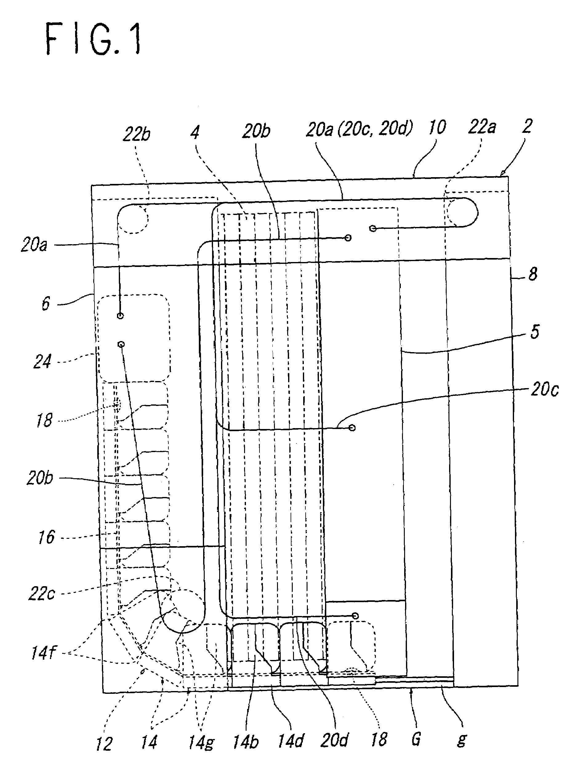
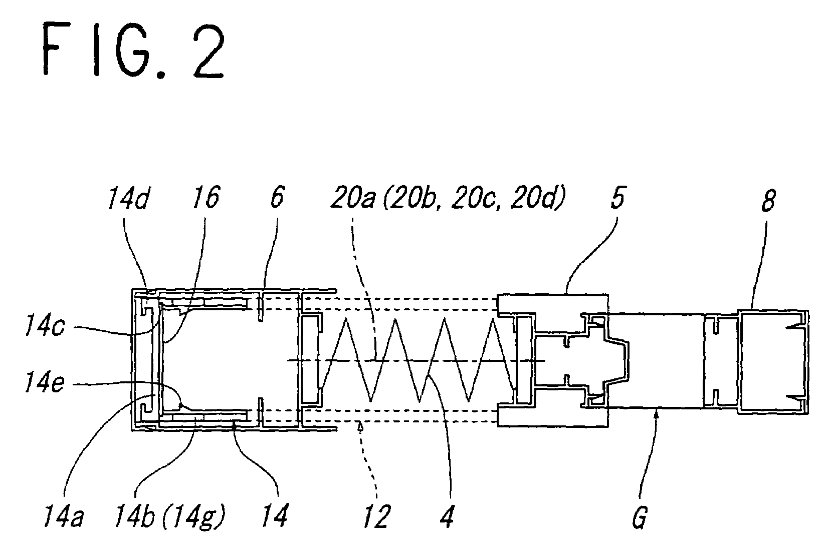
[0032]FIG. 1 to FIG. 3 show a sliding insect-blocking screen door according to the present invention.

[0033]This screen door is opened and closed by sliding a net that can be extended like an accordion and, as shown in FIG. 1, generally includes a screen door frame 2, an insect-blocking net 4 attached in the screen door frame 2 so as to be capable of the opening and closing by a sliding movement, and a movable edge member 5 mounted on one end of the net 4 for the opening and closing operation.

[0034]The aforementioned screen door frame 2 includes left and right vertical frame members 6 and 8, and an upper horizontal frame member 10, and the screen door frame 2 is provided with a net guide 12, for preventing shaking of the aforementioned net 4 at the lower portion thereof, so as to be fed out from and drawn into the lower end of the aforementioned vertical frame member 6 in association with the movement of the movable edge member 5. The net guide 12 is fixed to the lower end of the mov...

second embodiment

[0056]Subsequently, FIG. 5 and FIG. 6 show the sliding screen door according to the invention.

[0057]Although the sliding screen door of the second embodiment is the same as the aforementioned first embodiment in principal structure and, as shown in FIG. 5, guide pieces 34 are connected by the same type of tape member 36 as the aforementioned first embodiment while providing a sufficient length to the tape member 36 for bending a net guide 32 at the position where the net guide 32 is drawn out from the vertical frame member 6. Reference numeral 34a in FIG. 6 designates a bottom portion of the guide piece 34, reference numeral 34c designates an insertion device of the tape member 36, reference numeral 34d designates a guide ridge, and reference numeral 34f designates an abutting portion.

[0058]In other words, when the aforementioned net guide 32 is bent, the guide pieces 34 and 34 positioned at the bent portion are brought into contact with each other at the upper end corners of stabil...

third embodiment

[0060]FIG. 7 to FIG. 11 show a sliding screen door according to the present invention.

[0061]Although the principle structure of the sliding screen door according to the third embodiment is the same as the aforementioned first embodiment and the second embodiment, as shown in FIG. 7, a net guide 52 is constructed by connecting a plurality of guide pieces 54, which are detachably and rotatably connected with each other, and the same type of tape member 56, as the first and the second embodiment is inserted through these guide pieces 54.

[0062]The guide pieces 54 positioned at both ends of the net guide 52 are fixed to the aforementioned tape member 56, as in the case of the aforementioned first and second embodiments.

[0063]More specifically, the guide pieces 54 constituting the aforementioned net guide 52 are formed into a substantially U-shape, as clearly shown in FIGS. 10(a) to (e) and FIG. 11, and each include a bottom portion 54a extending along the lower end of the net 4 and a pai...


PUM


Abstract

The invention provides a sliding screen door having a net guide that moves in association with the opening and closing movement of a net, wherein the opening and closing operation of the screen door can be performed smoothly while providing a buffering effect with an adequate resistance, without hindering the opening and closing operability of a movable edge member, by enabling a reaction force, which is required for its bending, to be used as a buffering force against the operating force of the movable edge member, the net guide being formed by connecting guide pieces. In order to do so, a net guide 12 fed out from and drawn into the lower end of the vertical frame member 6 in association with the opening and closing operation of the net 4, is provided for guiding the lower end of the net 4. The net guide 12 is formed by connecting with a tape member 16 a number of guide pieces 14 formed substantially into a U-shape with a bottom portion 14a and a stabilizing portion 14b. The tape member 16 is inserted into the insertion devices 14c on the guide pieces 14 and the guide pieces 14 at both ends are fixed to the tape member 16.

Description

TECHNICAL FIELD[0001]The present invention relates to a screen door in which elastic net folded alternately back and forth can be opened and closed by a sliding movement and, more specifically, to a sliding screen door having a net guide that is drawn out along the lower end of the net in association with the opening and closing operation of the net.BACKGROUND ART[0002]A screen door constructed in such a manner that the left and right sides of a net, which is folded alternately back and forth and hence is elastic, are attached to a vertical frame member of a screen door frame and to a movable edge member for the opening and closing operation, and the aforementioned net is opened and closed by sliding the movable edge member, wherein a net guide that is drawn out from the lower end of either the aforementioned vertical frame member or the movable edge member along the lower end of the net in association with the opening and closing operation of the aforementioned net and that guides ...

Claims


Application Information

Patent Timeline
Patent Type & Authority Patents(United States)
IPC IPC(8): E06B9/262E06B9/52
CPCE06B9/262E06B9/52E06B2009/2625E06B3/92
Inventor AOKI, TAKASHI
Owner SEIKI JUKO
Why Eureka
Try Eureka