
Pipe joint

a technology for pipes and joints, applied in the field of pipes, can solve problems such as complicated work, and achieve the effect of increasing the safety and endurance of the joint body

Active Publication Date: 2005-12-27
TOZEN CORP
View PDF12 Cites 13 Cited by
  • Summary
  • Abstract
  • Description
  • Claims
  • Application Information

AI Technical Summary

Benefits of technology

[0004]The object of this present invention is, in view of the problems described above, to provide a pipe joint not requiring a reinforcement member, not bearing a load unfavorable to piping and the like, even when fluid pressure is exerted on the joint body, having a joint body with an increased safety and endurance, and capable of getting rid of complicatedness in attaching the flanges to the joint body.
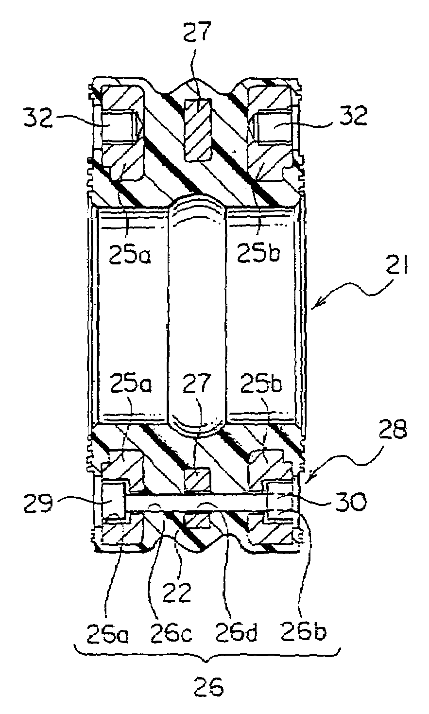
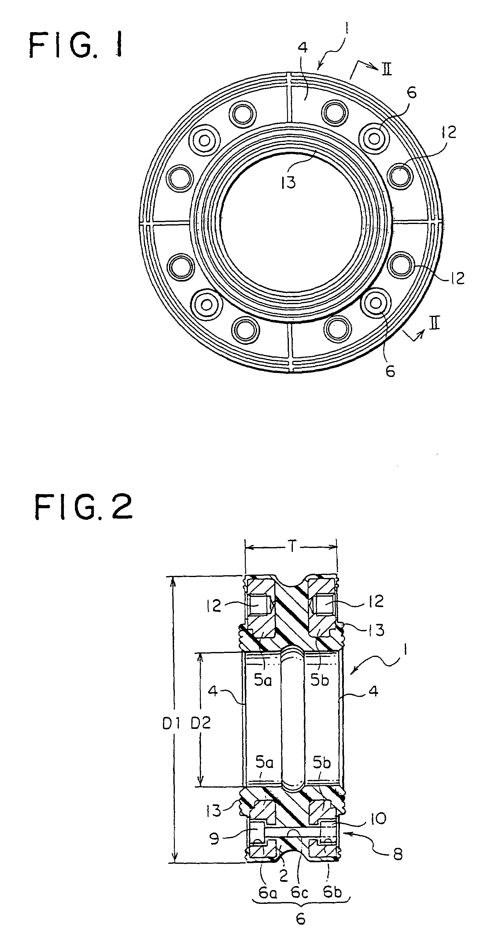
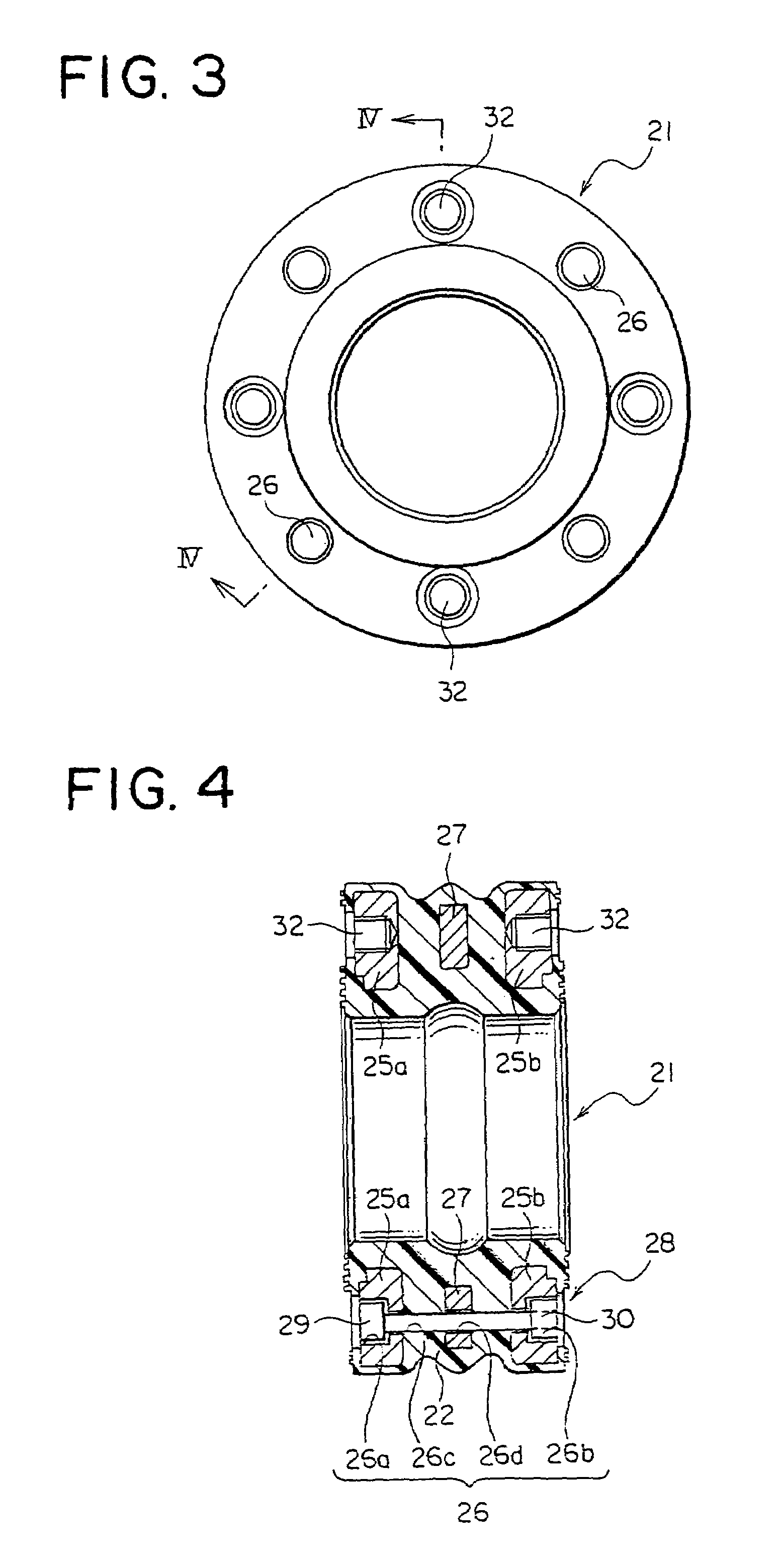
[0006]The pipe joint according to this invention has the configuration as described above so that, even when fluid pressure is exerted on the joint body, connecting both flanges to the joint body with the connecting appliance makes it possible to prevent the joint body from spreading axially, not bearing a load unfavorable to piping and the like. Further, this can increase safety and endurance of the joint body. In addition to no need for embedding a reinforcement member into the joint body in order to keep the shape of the same, the work of attaching flanges is not necessary.

Problems solved by technology

In addition, when both flanges 56 are attached to the joint body 53, it is necessary to crush both ends of the joint body for fitting the flanges thereinto, which makes the work complicated.

Method used


Image

  • Pipe joint
  • Pipe joint
  • Pipe joint

Examples


Embodiment Construction

[0013]One embodiment of the present invention is described with reference to the drawings.

[0014]In FIGS. 1 and 2, the reference numeral 1 indicates a pipe joint comprising a hollow cylindrical joint body 2. The joint body 2 is made of thick elastic material having a capacity to resist pressure. At both ends inside the joint body 2 are embedded metallic circular flanges 5a, 5b each having the same shape. In the direction of the circumference of the flanges 5a, 5b and the joint body 2 are provided a plurality of through holes 6 communicating axially at prescribed intervals. In the flanges 5a, 5b, the through holes 6 are formed to be shoulder holes 6a, 6b, 6a being larger than 6b, while in the joint body 2, the through hole 6 is formed to be a shoulder hole 6c having the same diameter as that of the shoulder hole 6b. In the through hole 6 is inserted a bolt-nut 8 as a connecting appliance. Namely, the bolt-nut 8 specifically comprises a through bolt 9 and a nut 10, the head of the bolt...


PUM


Abstract

A pipe joint is made up of a hollow cylindrical joint body made of an elastic material with a prescribed length, a circular flange embedded into each of the ends of the joint body, through holes provided axially at prescribed intervals in the direction of the circumference of the flanges and the joint body, and both flanges connected to the joint body with a connecting appliance penetrating into these through holes.

Description

FIELD OF THE INVENTION[0001]The present invention relates to a pipe joint for connecting piping used for fluid circulation.BACKGROUND OF THE INVENTION[0002]In a fluid circulation system as shown in FIG. 5, in order to minimize transmission of vibration generated in a power unit 50, such as a pump and a motor, to a piping system 51 as much as possible, the power unit 50 and the piping system 51 are connected via a pipe joint 52 having excellent vibration insulation properties. As the pipe joint 52, those such as the one shown in FIG. 6 are employed. This pipe joint 52 comprises a joint body 53 made of an elastic material, such as rubber, and a reinforcement member 54 made of a synthetic fiber or the like and embedded into the radial thickness of the joint body 53. Further, onto both openings 55, 55 of the joint body 53 are attached metallic flanges for connection 56, 56.[0003]The pipe joint 52 as described above according to the conventional technology, however, inevitably needs to e...

Claims


Application Information

Patent Timeline
Patent Type & Authority Patents(United States)
IPC IPC(8): F16L23/024F16L23/026F16L23/028F16L27/10F16L27/107F16L27/11F16L55/04
CPCF16L27/1012F16L27/107F16L27/11
Inventor MUROI, AKIRAKUWATA, TATEYUKIOYAMA, MITSUHIRO
Owner TOZEN CORP
Learn More