Toroidal-type continuously variable transmission

Active Publication Date: 2005-12-27
NSK LTD
View PDF18 Cites 3 Cited by
  • Summary
  • Abstract
  • Description
  • Claims
  • Application Information

AI Technical Summary

Benefits of technology

[0027]The present invention aims at eliminating the drawbacks found in the above-mentioned conventional toroidal-type continuously variable transmission. Accordingly, it is an object of the invention to provide a toroidal-type continuously variable transmission in which a tru

Problems solved by technology

However, in the above lubricating oil passage forming method, there arises a problem.
Therefore, even when the number of steps for working the trunnion 6 and trunnion sh

Method used


Image

  • Toroidal-type continuously variable transmission
  • Toroidal-type continuously variable transmission
  • Toroidal-type continuously variable transmission

Examples


Example

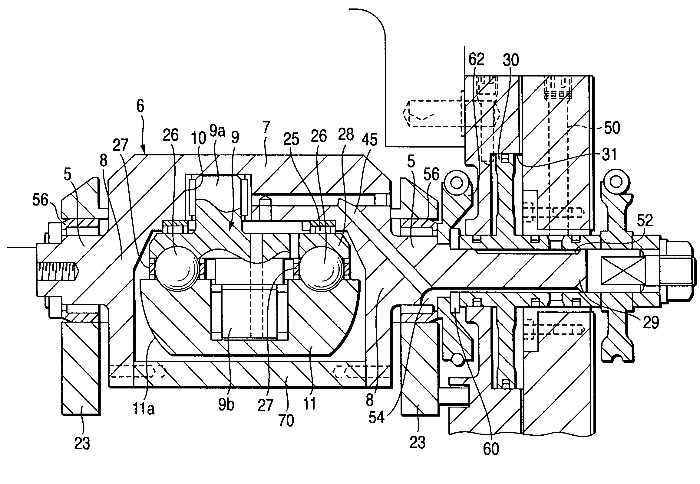
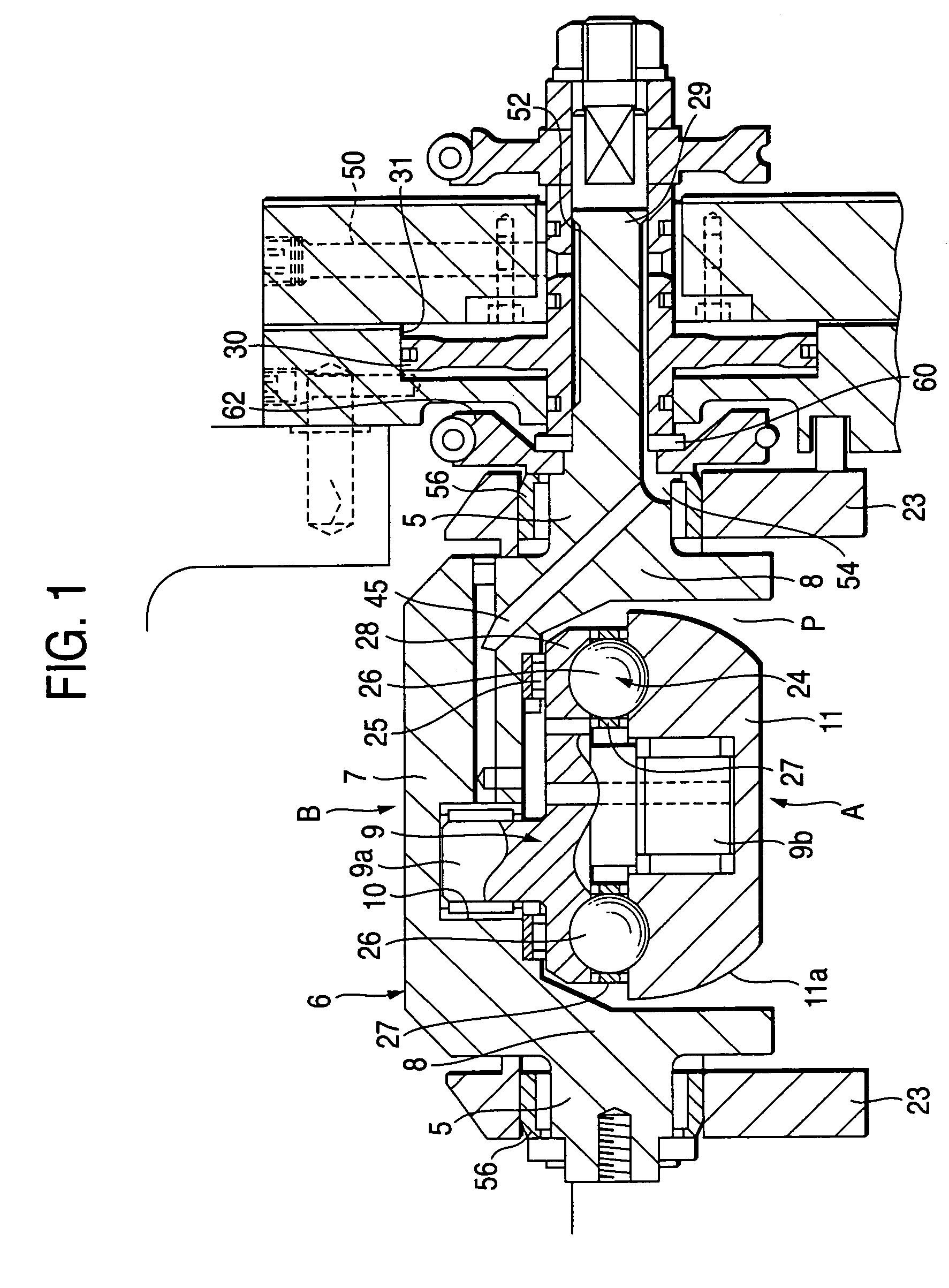
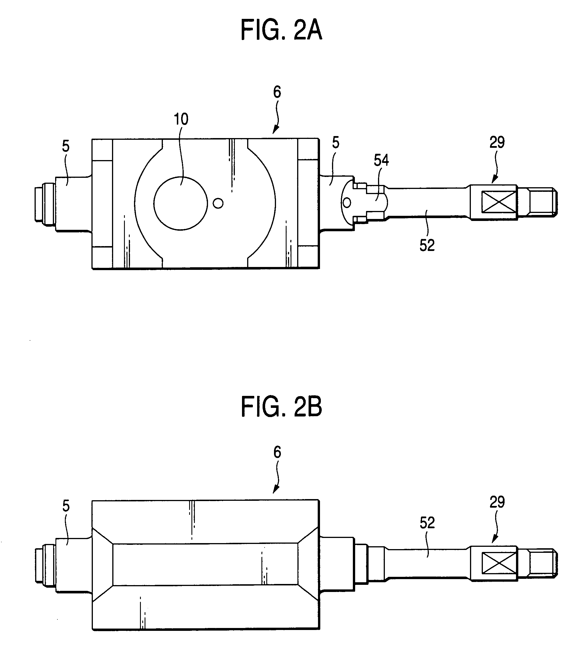
[0048]Now, description will be given below of an embodiment of a toroidal-type continuously variable transmission according to the invention. By the way, the invention has features relating an embodiment for forming a trunnion and a trunnion shaft of the toroidal-type continuously variable transmission and also an embodiment for forming an oil passage in the trunnion shaft; and, the remaining portions of the structure and operation of the invention are similar to those of the previously described conventional structure. Therefore, description will be given below only of the features of the invention, while the other portions thereof are given the same designations as in FIGS. 4 to 7 and thus the detailed description thereof is omitted here.

[0049]Now, FIGS. 1 and 2 show an embodiment of a toroidal-type continuously variable transmission according to the invention. As shown in FIGS. 1 and 2, a trunnion 6 constituting a toroidal-type continuously variable transmission according to the ...


PUM


Abstract

A toroidal-type continuously variable transmission, includes: a trunnion including: a support plate portion; and a pair of bent wall portions formed in longitudinal-direction two end portions of the support plate portion and bent on an inner surface side of the support plate portion, the pivot shafts being disposed concentrically with each other on outer surfaces of the bent wall portions; a trunnion shaft formed integrally with the pivot shaft; an oil pressure piston fitted with an outer peripheral surface of the trunnion shaft for moving the trunnions along the axial direction of the pivot shaft; and, a cut-away portion formed in the outer peripheral surface of the trunnion shaft for forming, between the cut-away portion and the oil pressure piston, an oil passage for a lubricating oil to be supplied to the bearing for a power roller.

Description

BACKGROUND OF THE INVENTION[0001]1. Field of the Invention[0002]The present invention relates to a toroidal-type continuously variable transmission which can be used as a transmission for a vehicle or various kinds of industrial machines.[0003]2. Description of the Related Art[0004]As a transmission for a vehicle, use of such a toroidal-type continuously variable transmission as schematically shown in FIGS. 4 and 5 has been executed in part of the vehicle industry. In this toroidal-type continuously variable transmission, for example, as disclosed in JP-UM-A-62-71465, an input side disk 2 serving as a first disk is supported concentrically with an input shaft 1, and an output side disk 4 serving as a second disk is fixed to the end portion of an output shaft 3 which is disposed concentrically with the input shaft 1. In the interior of a casing in which the toroidal-type continuously variable transmission is stored, there are disposed trunnions 6, 6 which can be respectively swung ab...

Claims


Application Information

Patent Timeline
IPC IPC(8): F16H15/38
CPCF16H15/38F16H57/043F16H57/049
Inventor ISHIKAWA, KOUJIIMANISHI, TAKASHI
Owner NSK LTD
Why Eureka
Try Eureka