Illuminated vehicle remote entry device

a remote entry device and keypad technology, applied in the direction of identification means, electrical apparatus casings/cabinets/drawers, instruments, etc., can solve the problems of uneven distribution of lighting on each button, limited packaging of lighting elements in the rke fob, and not so easily visible during night hours, so as to minimize the number of components required. , the effect of lighting the display area of the rke fob

Inactive Publication Date: 2005-12-27
LEAR CORP
View PDF11 Cites 55 Cited by
  • Summary
  • Abstract
  • Description
  • Claims
  • Application Information

AI Technical Summary

Benefits of technology

[0009]The present invention has the advantage of illuminating a display area of a RKE fob using EL lighting while minimizing the number of components required to illuminate the display area.

Problems solved by technology

While these graphical displays are easily visible the daylight, they are not so easily visible during night hours in less ambient light.
To assist the operator in viewing the buttons of the RKE fob during poor lighting conditions, lighting schemes may be added to the RKE fob for illumination purposes, however the packaging of lighting elements in the RKE fob are limited due to size and packaging constraints.
An individual LED used to illuminate more than one button often produces uneven distribution of lighting on each button.
Keypads made with EL film may be inserted through fascia button holes for illumination, however, this creates separate and distinct components within the RKE fob and may be subject to misalignments when assembled.
Stack-up and dimensional tolerancing issues are potential manufacturing problems when a first component is inserted into a second component.
For example, a separate keypad having a plurality of buttons inserted into a fascia having a plurality of apertures to receive the plurality of buttons may result in misalignments due to dimensional tolerances of the two separately molded components.

Method used


Image

  • Illuminated vehicle remote entry device
  • Illuminated vehicle remote entry device
  • Illuminated vehicle remote entry device

Examples


Embodiment Construction

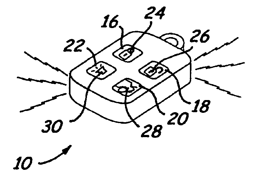
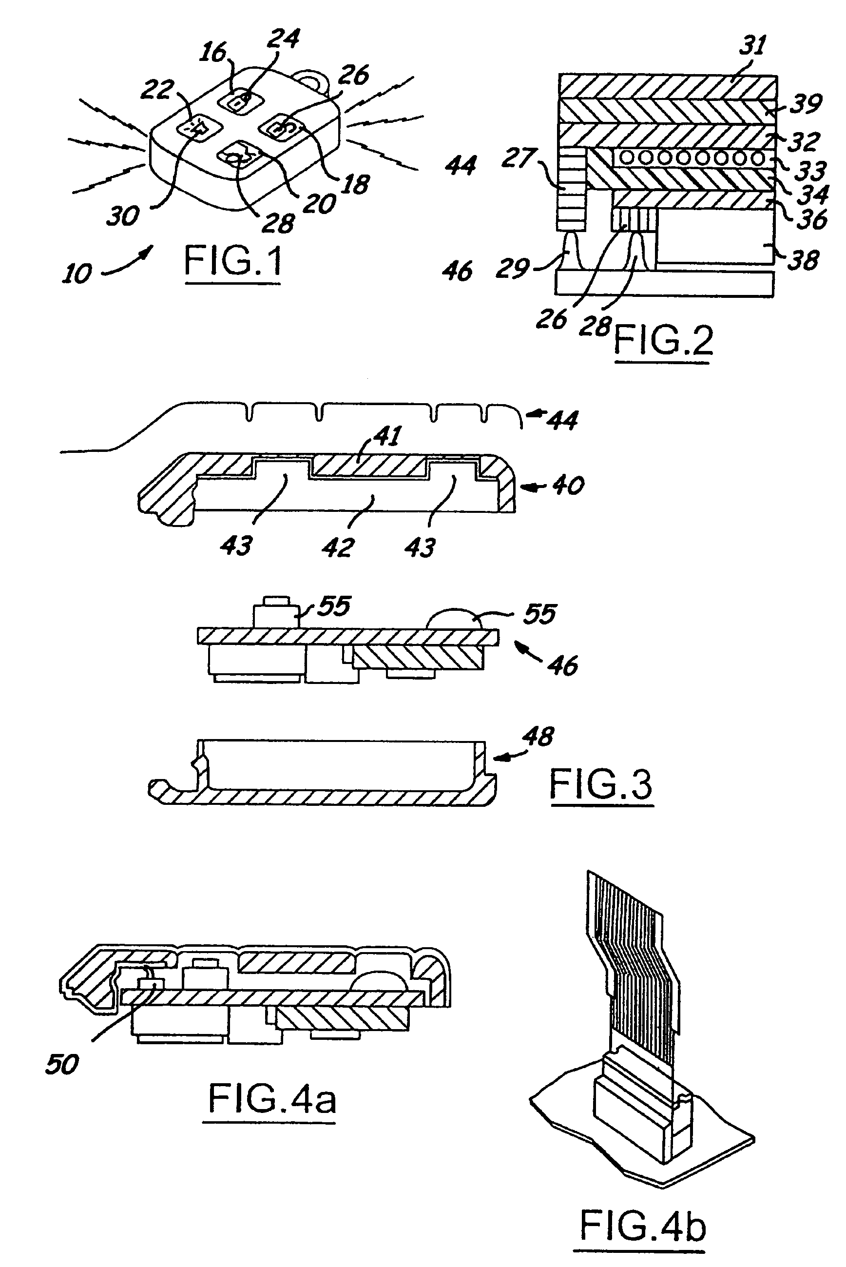
[0021]FIG. 1 shows a remote vehicle interface device such as a remote keyless entry (RKE) fob 10 that broadcasts RF signals for unlocking and locking a vehicle door, unlatching a trunk latch, and for activating and deactivating a vehicle alarm system. A vehicle lock switch 16 and a vehicle unlock switch 18 are commonly disposed on a face of the RKE fob 10. The RKE fob 10 may further include a trunk unlatch switch 20 and alarm switch 22 for activating and deactivating the vehicle alarm. Graphics are typically printed on the face of a respective switch identifying the functionality of each respective switch. For example, the lock switch 16 may have a locked padlock graphic design 24, and the unlock switch 18 may include an unlocked padlock graphic design 26. Likewise, the trunk unlatch switch 20 may have an open trunk graphic 28 and the alarm switch 22 may have a siren graphic 30. RKE fobs may include other buttons for vehicle functionality such as open / close sliding door, remote star...


PUM


Abstract

A remote keyless entry electroluminiescent (EL) device includes at least one depressible button segment for activating a vehicle function. The entry device includes an upper housing with at least one aperture in the upper housing. An EL film is integral to the upper housing for illuminating at least one display area. A printed circuit board is disposed under the upper housing. An electrical contact is provided for supplying a power source from the printed circuit board to the EL film for illumination. A lower housing is adjoined to the upper housing, the upper housing and the lower housing encasing the printed circuit board wherein the EL film is in-molded as part of the upper housing for forming a single component.

Description

CROSS REFERENCE TO RELATED APPLICATIONS[0001]Not Applicable.STATEMENT REGARDING FEDERALLY SPONSORED RESEARCH[0002]Not Applicable.BACKGROUND OF THE INVENTION[0003]1. Field of the Invention[0004]The present invention relates in general to an electroluminiescent (EL) lighting, and more specifically, to illuminating a keypad of a remote vehicle entry transmitter.[0005]2. Description of the Related Art[0006]Remote vehicle entry transmitters are used for performing a wireless operation on a vehicle such as locking and unlocking a door, unlatching a trunk latch, or activating or deactivating an alarm system equipped on the vehicle. These remote entry devices are commonly referred to a remote keyless entry (RKE) fob. The RKE fob is carried with the operator of a vehicle and can wirelessly perform these functions when within a predetermined reception range of the vehicle. The RKE fob is typically a small rectangular or oval plastic housing with a plurality of depressible buttons for activati...

Claims


Application Information

Patent Timeline
Patent Type & Authority Patents(United States)
IPC IPC(8): B60R25/10G07C9/00G09G5/00H01H9/00H01H9/02H01H9/18H04M1/00H05K7/02
CPCG07C9/00944H01H9/182G07C2009/00222H01H9/0235H01H2009/186Y10S345/905
Inventor WRIGHT, JAMES B.PAGANO, LEONARD E.
Owner LEAR CORP
Why Eureka
Try Eureka