Communications terminal

Inactive Publication Date: 2005-12-27
QISDA CORP
View PDF15 Cites 8 Cited by
  • Summary
  • Abstract
  • Description
  • Claims
  • Application Information

AI Technical Summary

Benefits of technology

[0006]According to the present invention, the antenna element and the acoustic output device of the communications terminal are designed and / or arranged with respect to each other in such a way that at least part of the antenna volume forms at least part of a resonant cavity for the acoustic output device; for example, an earpiece. As a result of the present invention, the space available in the communications terminal is utilized very effectively in that the space required for the antenna function is simultaneously optimized and designed as a resonant cavity. As such, the space inside the communications terminal is used for two different functions without impairments to the one function arising from the use for the other function. For the antenna function, an air-filled interior cavity area is optimum, because such an air-filled area only has a small dielectric constant and does not cause any RF losses at all. The acoustics also need as large an air-filled area as possible as resonant cavity for optimum operation; for example, as a “back-cavity” volume at the back of an earpiece.
[0011]For maximum efficiency when fitting such an antenna support having the antenna element and the acoustic output device, the antenna support preferably also contains contact elements for making conductive contact with the antenna element and / or the acoustic output device and / or the screened cavity. The antenna support having the applied antenna elements, the pre-fitted acoustic output device (or, specifically, earpiece), and the finished screened cavity with the associated contact elements, can simply be placed as a prefabricated module at the required position on the circuit board during final assembly of the communications terminal. By designing the contact elements to the circuit board to be elastic so as to create pressure contacts, other additional work operations such as contact soldering can be avoided.

Problems solved by technology

Since the antenna elements in more modern devices are preferably integrated in the device, the communications terminal takes up a larger amount of space.
In addition, the requirement for communications terminals with dual-band capability or multi-band capabilities means that the antennas need to occupy even more space.

Method used


Image

  • Communications terminal
  • Communications terminal
  • Communications terminal

Examples


Embodiment Construction

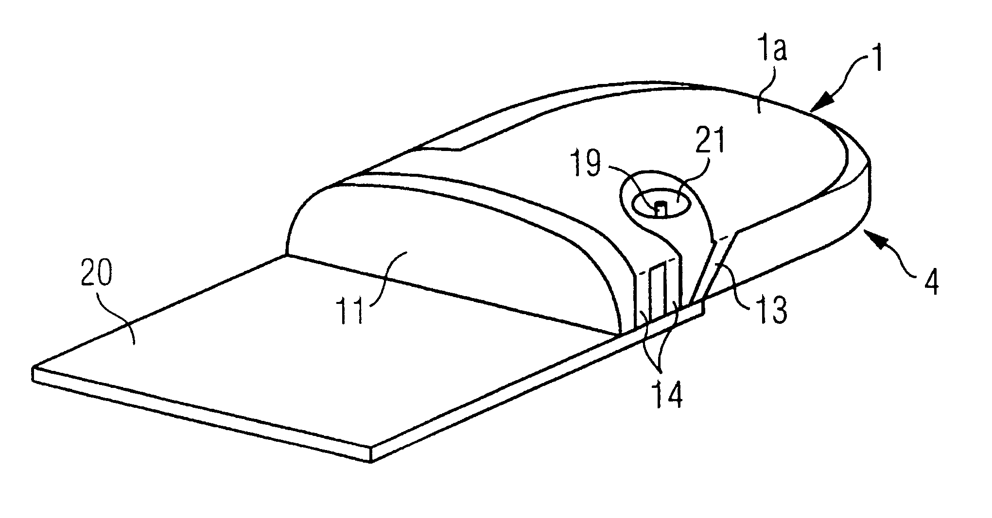
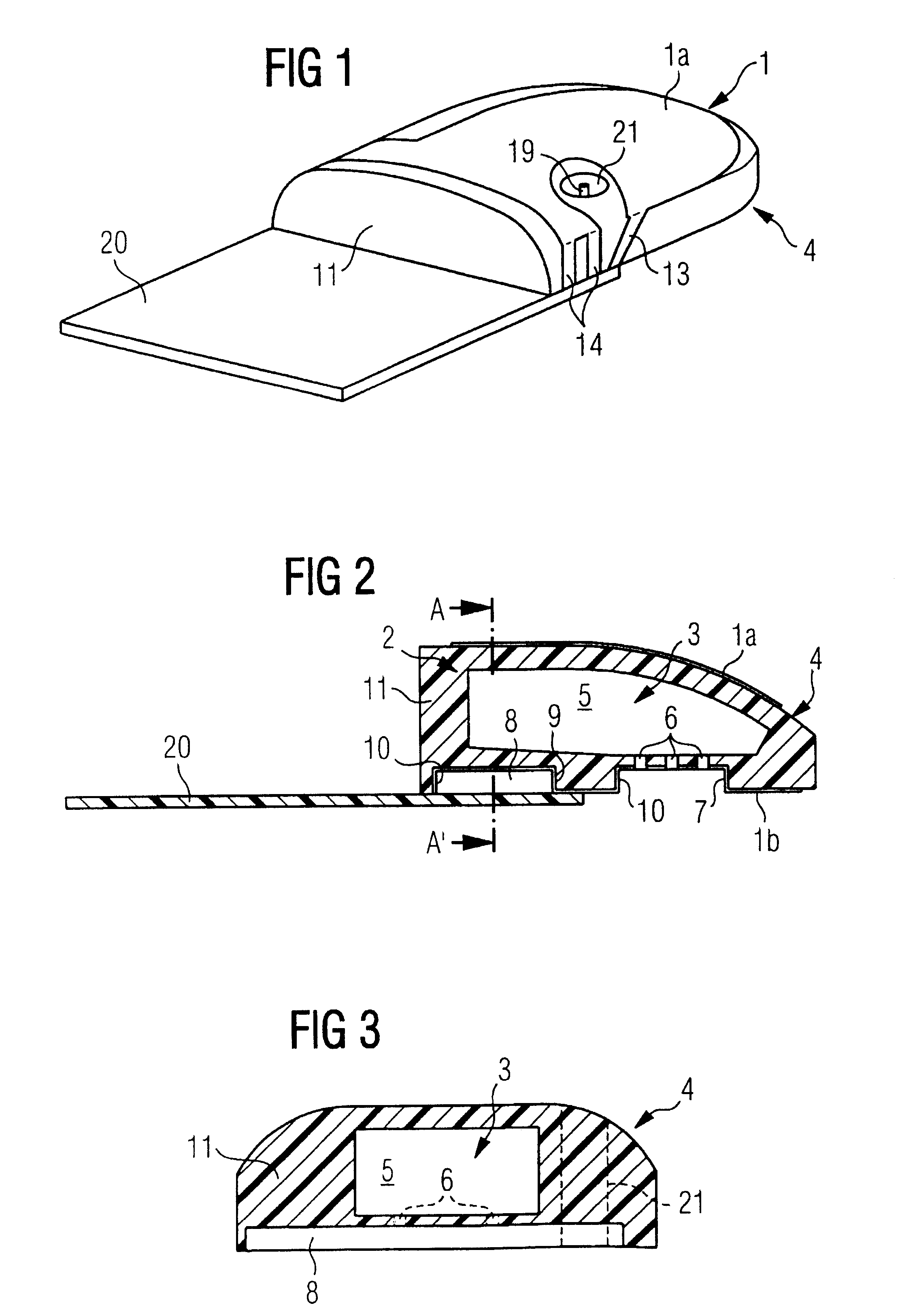
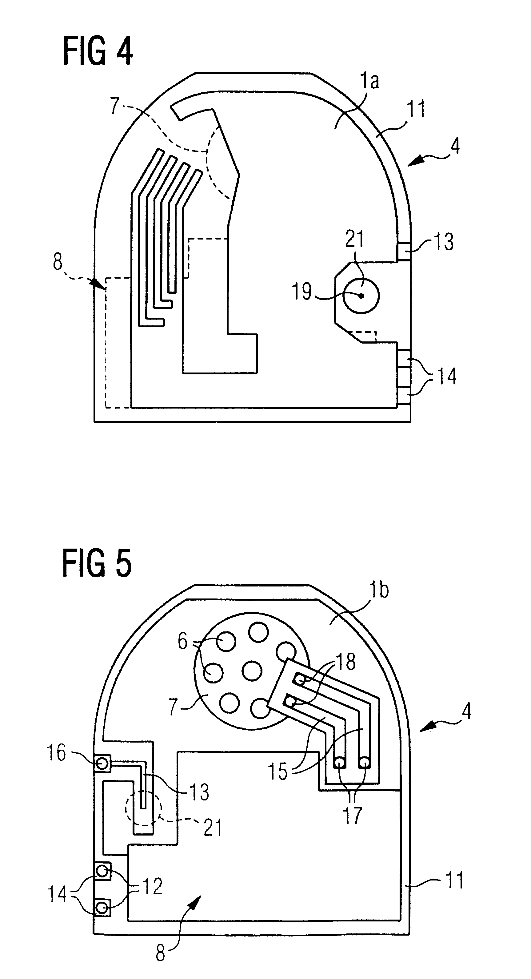
[0018]The figures show an antenna module for a communications terminal according to the present invention; specifically, a mobile phone. This module has an antenna support 4 which is basically formed as a non-conducting plastic body 11. This antenna support 4 is coated on two opposite surfaces with specially patterned conducting areas 1a, 1b forming a two-piece antenna element 1. The antenna volume extends between the conducting areas 1a, 1b. This antenna module is placed in suitable contact with a printed circuit board 20 of the mobile phone at the intended position in the mobile phone.

[0019]The design and shape of the antenna module are described in detail below.

[0020]The plastic body 11 forming the antenna support 4 consists of two joined half-shells, which thereby create a cavity 5 inside the plastic body 11. For good sound quality, the resonant cavity 3 should have a maximum volume. The cavity 5 is therefore chosen to be as large as possible, while taking care that the remainin...


PUM


Abstract

A communications terminal is provided which includes an antenna element, which has a specific antenna volume, and an acoustic output device, wherein the antenna element and the acoustic output device are designed and / or arranged with respect to each other such that at least part of the antenna volume forms at least part of a resonant cavity for the acoustic output device.

Description

[0001]This application is a 371 of PCT / D E01 / 03615 Sep. 19, 2001.BACKGROUND OF THE INVENTION[0002]The present invention relates to a communications terminal having an antenna element, which has a specific antenna volume, and an acoustic output device.[0003]In the development of modern communications terminals, particularly mobile handheld devices such as mobile phones, palmtops or PDAs (Personal Digital Assistants) having appropriate mobile radio functions, minimizing the overall dimensions of the device is increasingly important. At the same time, the device is meant to offer ever more facilities with ever better quality, including optimizing the reproduction quality of the transmitted signals. Apart from improving the microphone of the transmitting communications terminal, this also requires the best possible transmission quality of the signal over the air interface, and a qualitatively good acoustic output device in the receiving device.[0004]Crucial for the transmission quality ...

Claims


Application Information

Patent Timeline
IPC IPC(8): H01Q1/24H01Q1/44H01Q9/04H04B1/3827H04M1/02H04M1/03
CPCH01Q1/243H01Q1/44H01Q9/0407H04B1/3833H04M1/0202H04M1/035
Inventor NEVERMANN, PETER
Owner QISDA CORP
Why Eureka
Try Eureka