
Methods and apparatus for shading object drawings in video games

a technology of object drawing and video game, applied in the field of video game, can solve the problem that objects are difficult to recognize in the projection image drawn, and achieve the effect of enhancing objects and facilitating recognition of objects in images

Inactive Publication Date: 2005-12-27
SQUARE ENIX HLDG CO LTD
View PDF13 Cites 1 Cited by
  • Summary
  • Abstract
  • Description
  • Claims
  • Application Information

AI Technical Summary

Benefits of technology

[0006]An object of the present invention is to enhance the object by shading part of the contours of the object, so as to facilitate recognition of the object in the image.
[0008]The part of the dummy object not overlapping with the object when observed from the view point is drawn in the lightness different from that of the object, i.e., so as to be brighter or darker than the object. For example, where the whole virtual space is dark and the part of the dummy object not overlapping with the object when observed from the view point is drawn so as to be brighter than the object, the contour part of the object is drawn in a brighter color. Therefore, the above method can enhance the object, so as to facilitate the recognition of the object in the image.
[0015]The program can be made so that the computer executes the object drawing method in the video game according to either of the first to the third aspects of the present invention. In that case, the above-stated modifications for the first to the third aspects can also be applied to the program. The program according to the present invention is stored in a storage medium or a storage device, for example, such as the CD-ROM, floppy disc, memory cartridge, memory, hard disc, and so on. The video game apparatus described below can be realized by making the computer read in the program stored in the storage medium or storage device. The storage media permit the program according to the present invention to be distributed and sold readily as software products independent of the apparatus. Further, when the program is carried out by the hardware such as the computer or the like, the technology of the present invention can be carried out readily by the hardware such as the computer or the like.

Problems solved by technology

When the projection image is drawn so as to accurately reflect the result of the luminance computation in this way, there occurs some cases wherein the object becomes hard to recognize in the projection image drawn.

Method used


Image

  • Methods and apparatus for shading object drawings in video games
  • Methods and apparatus for shading object drawings in video games
  • Methods and apparatus for shading object drawings in video games

Examples


embodiment 1

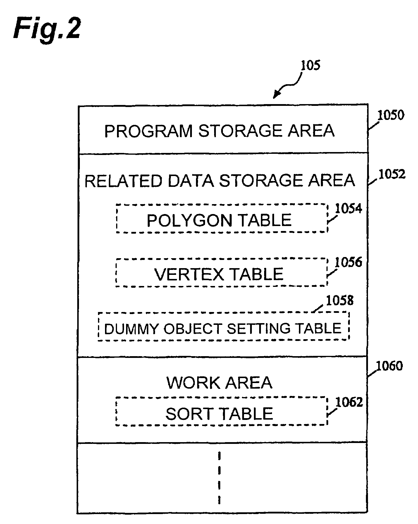
[0049]FIG. 2 shows a state of the RAM 105, for example, where the program and data according to the embodiment 1 of the present invention, which were stored in the CD-ROM 131, are loaded on the RAM 105 by the CD-ROM drive 113 and the program according to the present invention is under execution. In the present embodiment 1 the RAM 105 consists of at least a program storage area 1050, a related data storage area 1052, and a work area 1060. The program saved in the program storage area 1050 will be described hereinafter. The related data storage area 1052 includes a polygon table 1054, a vertex table 1056, and a dummy object setting table 1058. The work area 1060 includes a sort table 1062.

[0050]An example of the polygon table 1054 included in the related data storage area 1052 is presented in FIG. 3. The polygon table 1054 is a table for specifying an object or objects to be drawn, polygons constituting each object, and vertexes constituting each of the polygons. For specifying each ...

embodiment 2

[0120]Embodiment 1 employed the hidden surface removal using the Z sort method in the drawing process, whereas the present embodiment 2 employs the hidden surface removal using the Z buffer in the drawing process.

[0121]In the present embodiment 2, FIG. 14 shows a state of the RAM 105, for example, where the program and data according to the embodiment 2 of the present invention, which were stored in the CD-ROM 131, are loaded in the RAM 105 by the CD-ROM drive 113 and the program according to the embodiment 2 of the present invention is executing. In the present embodiment the RAM 105 consists of at least the program storage area 1050, the related data storage area 1052, and the work area 1060. The program saved in the program storage area 1050 will be described hereinafter.

[0122]The related data storage area 1052 includes the polygon table 1054, the vertex table 1056, and the dummy object setting table 1058. The structure so far is the same as in Embodiment 1. The work area 1060 in...

modification 1

(Modification 1)

[0160]In the above description, each object was described as a whole model of a character in the video game. However, an object is allowed to be handled as part of a model. For example, it is also possible to set objects in partial units of the head, chest, right arm, left arm, etc. in a human game character and execute the processing of shading operation in the object units. When the objects are set in the partial units, thicknesses of edges to be subjected to shading can be set finely by setting the lightness adjustment values and the depth adjustment value for each part.


PUM


Abstract

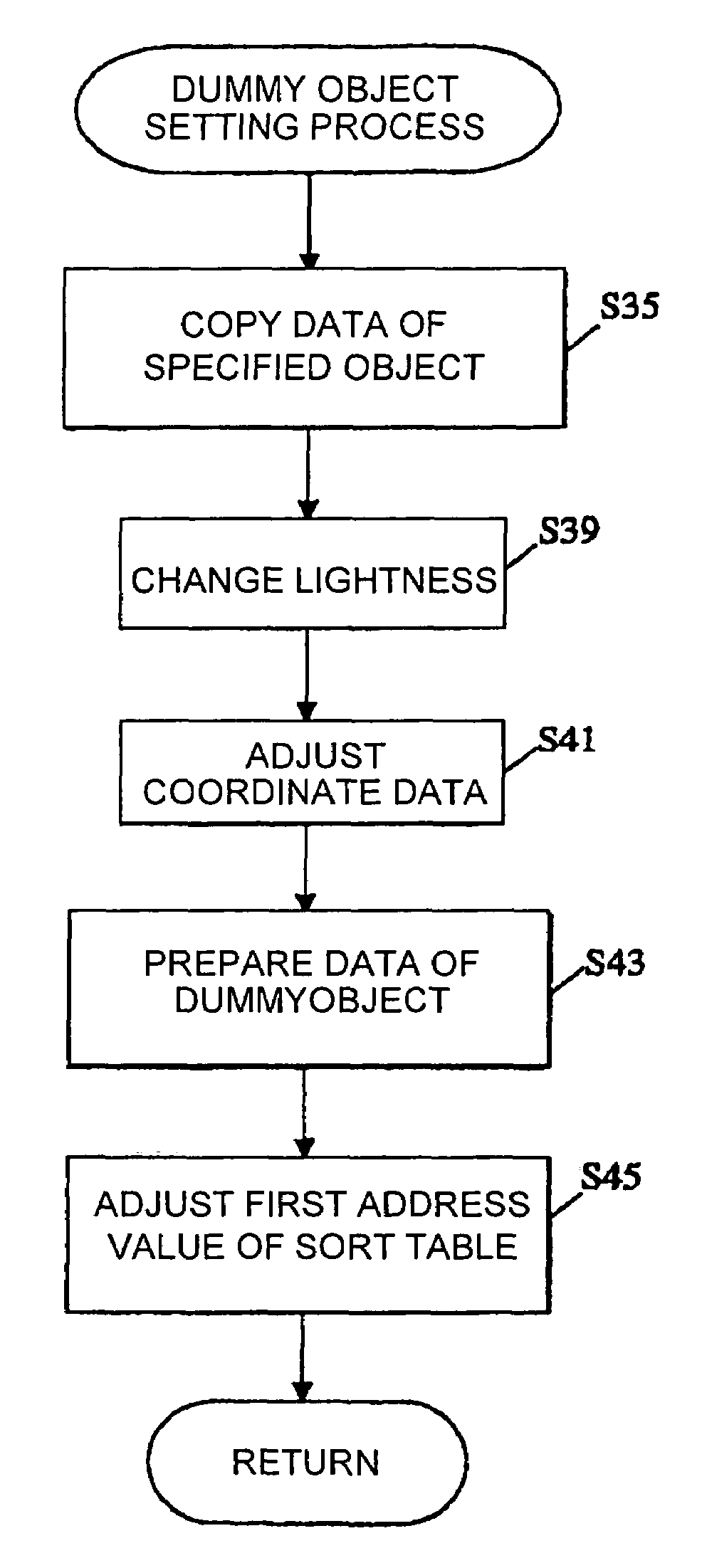
A dummy object is generated by copying an object. A color of the dummy object is set to be brighter than the object and the position of the dummy object is finely adjusted. After that, the object and the dummy object are drawn using the Z sort method. Polygons of the object are added to a sort table as usual, whereas polygons of the dummy object are added to the sort table after such a shift of the first address of the sort table as to locate them behind their actual depth value with respect to the view point. Since the polygons are drawn from the farthest polygon from the view point in the sort table, the object is drawn over the dummy object. In the last stage the dummy object remains only in the part projecting outside the object and the part is drawn in a brighter color than the object.

Description

BACKGROUND OF THE INVENTION[0001]1. Field of the Invention[0002]The present invention relates to a video game and, more particularly, the technology for shading an object in a virtual space.[0003]2. Related Background Art[0004]In recent years a variety of rendering techniques have been studied for shading in the surface of the object placed in a virtual, three-dimensional space in the field of video games. For shading the object placed in the virtual 3D space, luminance computation is executed in consideration of various factors including the property of a light source, the positional relation among the light source, the object, and the view point, the texture of the surface of the object, and so on. Then realistic shading can be made for the image by drawing the image after transparent transformation, based on the result of the luminance computation.[0005]However, the phenomena described below can be encountered when the projection image is drawn so as to accurately reflect the res...

Claims


Application Information

Patent Timeline
IPC IPC(8): A63F13/45A63F13/55G06T15/00G06T15/02G06T15/80G06T19/00
CPCA63F13/00G06T15/80A63F2300/66
Inventor MINAGAWA, HIROSHITSUCHIDA, YOSHINORI
Owner SQUARE ENIX HLDG CO LTD
Learn More