Objective lens system

a lens system and objective technology, applied in the field of objective lens systems, can solve the problems of low producibility or high manufacturing cost, difficult to correct offaxial aberration, and inability to produce high optical performance from two homogeneous spherical lens elements, etc., to achieve wide field angle and favorable correction of aberrations

Inactive Publication Date: 2005-12-27
OLYMPUS CORP
View PDF16 Cites 10 Cited by
  • Summary
  • Abstract
  • Description
  • Claims
  • Application Information

AI Technical Summary

Benefits of technology

[0009]A primary object of the present invention is to provide an objective lens system which is composed of lens elements in a number on the order of 2, that favorably corrects aberrations and has a wide field angle.

Problems solved by technology

Though this conventional example favorably corrects aberrations, it is composed of lens elements in a number as large as six, thereby posing a problem of low producibility or a high manufacturing cost.
However, a lens system which favorably corrects aberrations and has high optical performance can hardly be composed of two homogenous spherical lens elements.
Accordingly, axial aberrations do not pose a serious problem, but a wide field angle and a negative-positive asymmetrical composition as shown in FIG. 1 make it difficult to correct offaxial aberrations.
It is therefore difficult to favorably correct offaxial aberrations with two homogenous lens elements so as to obtain favorable offaxial imaging performance.
However, this conventional example has a field angle as narrow as 72° which is insufficient for use as an objective lens system for endoscopes.
Though this example uses a radial type gradient index lens element, it does not effectively make use of the chromatic aberration correcting capability of the radial type gradient index lens element and does not sufficiently correct lateral chromatic aberration which poses a problem in a lens system having a wide field angle in particular.

Method used


Image

  • Objective lens system
  • Objective lens system
  • Objective lens system

Examples


sixth embodiment

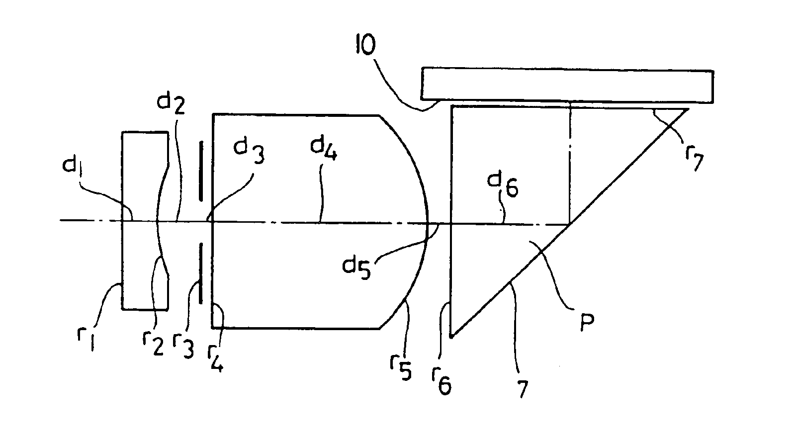
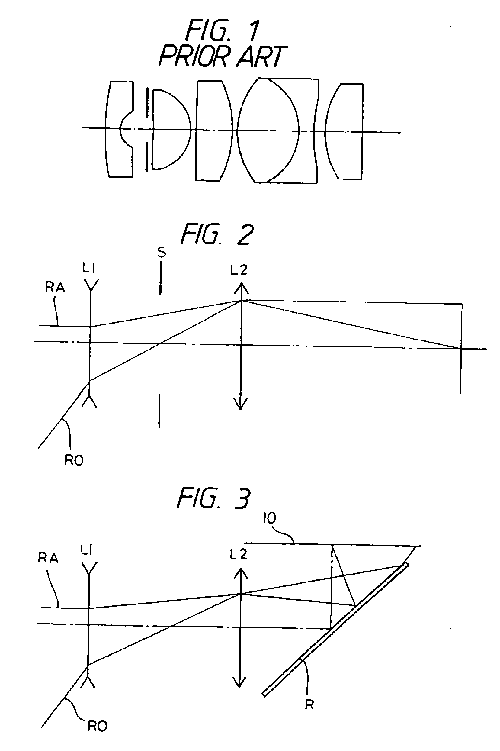
[0088]The objective lens system according to the present invention which has a sixth embodiment is characterized in that it is composed, in order from the object side, of a first lens unit having a negative refractive power and a second lens unit having a positive refractive power; that it uses at least one radial type gradient index lens element which has a refractive index distribution in a radial direction expressed by the formula (a); and it uses a reflecting surface for at least a single reflection disposed on the image side of the second lens unit.

[0089]Resolution of an optical system for endoscopes which uses a solid-state image pickup device such as a CCD, for example, can be enhanced by reducing the size of picture elements and arranging these picture elements in a larger number at a higher density on the image pickup device. However, the size of a picture element can be reduced only within a certain manufacturing limit and it is therefore conceivable to enhance resolution ...

first embodiment

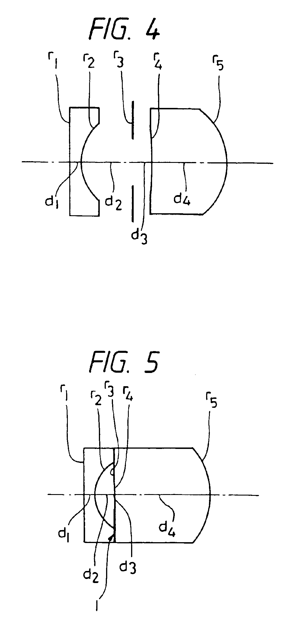
[0199]the objective lens system according to the present invention has a composition illustrated in FIG. 4. Speaking concretely, it is composed of two lens units, i.e., in order from the object side, a first lens unit consisting of a negative lens element, a stop and a second lens unit consisting of a positive lens element. The second lens unit having the positive refractive power is configured as a radial type gradient index lens element. The first lens unit is composed of a homogenous lens element which has a planar surface on the object side and a concave surface on the image side, whereas the second lens unit is composed of a radial type gradient index lens element having a meniscus shape which has a concave surface on the object side.

[0200]Though it is ordinarily difficult to favorably correct lateral chromatic aberration in particular with two lens elements, the lens system preferred as the first embodiment is capable of favorably correcting lateral chromatic aberration by usi...

second embodiment

[0205]the present invention is an objective lens system which has a composition illustrated in FIG. 5. Speaking concretely, it is composed of two lens elements, i.e., in order from the object side, a first lens unit composed of a negative lens element, a stop and a second lens unit composed of a positive lens element. The second lens unit having the positive refractive power is configured as a radial type gradient index lens element.

[0206]The second embodiment is an example in which the objective lens system is configured so as to have a total length that is shorter than that of the first embodiment. In the second embodiment also, lateral chromatic aberration in particular is favorably corrected by using the radial type gradient index lens element as the second lens unit.

[0207]The radial type gradient index lens element has a meniscus shape which has a concave surface on the object side. When a radial type gradient index lens element has such a meniscus shape, its refractive power o...


PUM


Abstract

An objective lens system consisting of a first lens unit having a negative refractive power and a second lens unit having a positive refractive power wherein the first lens unit or the second lens unit comprises at least one radial type gradient index lens element which has a refractive index distribution in a radial direction from an optical axis. This objective lens system favorably corrects chromatic aberration and other aberrations by adequately selecting a value expressing an Abbe's number and a refractive power of medium for the radial type gradient index lens element.

Description

CROSS REFERENCE TO RELATED APPLICATIONS[0001]This application is a Divisional of U.S. application Ser. No. 09 / 845,205, filed May 1, 2001, now U.S. Pat. No. 6,519,098, which is a Divisional of U.S. application Ser. No. 09 / 455,362, filed Dec. 6, 1999, now U.S. Pat. No. 6,243,217; and which is a Divisional of U.S. application Ser. No. 08 / 713,069, filed Sep. 12, 1996, now U.S. Pat. No. 5,999,327, the specifications and drawings of which are incorporated herein by reference.BACKGROUND OF THE INVENTION[0002]a) Field of the Invention[0003]The present invention relates to an objective lens system which uses a radial type gradient index lens element.[0004]b) Description of the Prior Art[0005]As conventional examples of lens systems having relatively wide field angles and high optical performance which are used, for example, as objective lens systems for endoscopes, there are known many lens systems such as a lens system disclosed by Japanese Patent Kokoku Publication No. Sho 60-46410 shown i...

Claims


Application Information

Patent Timeline
Patent Type & Authority Patents(United States)
IPC IPC(8): G02B13/04G02B3/00G02B9/10G02B13/00
CPCG02B3/0087G02B9/10G02B13/0025G02B13/003G02B13/0045G02B13/006G02B13/0065G02B23/24
Inventor NAGAOKA, TOSHIYUKI
Owner OLYMPUS CORP
Why Eureka
Try Eureka