Telecom circuit protection apparatus

a circuit protection and circuit technology, applied in the direction of overvoltage protection resistors, emergency protection arrangements for limiting excess voltage/current, overvoltage protection resistors, etc., can solve the problems of severely constraining the design parameters of fuse components, unwanted equipment failure, etc., to improve resistance and enhance protection performance.

Active Publication Date: 2005-12-27
BEL FUSE
View PDF13 Cites 3 Cited by
  • Summary
  • Abstract
  • Description
  • Claims
  • Application Information

AI Technical Summary

Benefits of technology

[0006]It is an object of the present invention to beneficially utilize the heat generated by a circuit protection device's voltage clamping component(s) under certain fault conditions. In particular, an object of the present invention is to employ material properties, thermodynamic principles and placement geometry to significantly enhance protection performance over prior art by allowing for the use of a more robust fusing device to better resist undesirable clearing when the apparatus is exposed to lightning surges within the suppression capabilities of its associated voltage clamping device, but exceeding regulatory survival thresholds. Due to aspects of the present invention, the fuse also retains the capability of opening within regulatory time limits when exposed to low current, power cross test conditions.
[0007]Another object of the present invention is to maximize the packaging density of the necessary protective circuit components such that the apparatus beneficially reduces the circuit board real estate required to add mandated protection to communications equipment.
[0008]Yet another object of the present invention is to reduce telecommunications equipment assembly cost by providing a modular, protection “solution” to equipment manufacturers that is both compatible with “surface mount” manufacturing techniques and can be automatically set on a circuit board in a single cycle using “pick & place” equipment.

Problems solved by technology

This implies that the fusing element should have a high enough I2t (energy let-through) to preclude its opening when exposed to “acceptable” surge levels resulting in unwanted equipment failure.
These conflicting requirements severely constrain the design parameters of the fuse.

Method used


Image

  • Telecom circuit protection apparatus
  • Telecom circuit protection apparatus
  • Telecom circuit protection apparatus

Examples


Embodiment Construction

[0019]All electronic components liberate some heat when in use. In the case of fuses or PTC's, this heat is vital to proper function and is a focal point of the present invention. When enough current is passed through a fuse link or PTC, the heat internally produced is able to overcome losses through its end connections and its surface to its surroundings and its element temperature is able to reach its fusing / high resistance point, opening the fuse or driving the PTC into its current limiting mode.

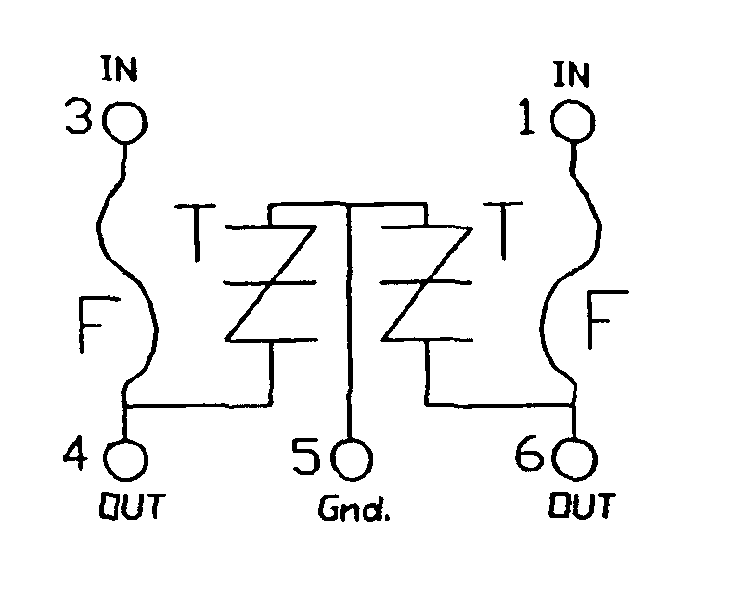
[0020]A semiconductor device, such as a thyristor, also liberates heat when in its conducting state. Power dissipated is the product of its forward voltage drop and the current passing through it. Most of the heat produced is shed through the device's soldered connections, with a lesser portion carried off by its surroundings. Unlike a fuse, excessive temperature rise can impair a semiconductor's proper function. Device junction temperature must be held below its manufacturer's stated max...


PUM


Abstract

A telecom circuit protection apparatus includes a housing having at least first and second temperature responsive circuit protection devices, such as a fuse and a thyristor disposed therein. A first metal lead is connected to respective first terminals of the first and second circuit protection devices and is structured and arranged such as to transfer heat freely between the second circuit protection device and the first circuit protection device. A second metal lead is connected to a second terminal of the first device and a third metal lead is connected to a second terminal of the second device. The first, second and third metal leads extend from the housing. Advantageously, the portions of the first, second and third metal leads extending from the housing have reduced cross-sections to reduce heat loss from the apparatus and are formed and made solderable for use as connection points for surface mount connection to the apparatus. To protect multiple service lines, a circuit protector is provided for each of them. In this case, the multiple circuit protectors may advantageously be collocated in a common housing having either a common or separate ground terminal(s).

Description

CROSS REFERENCE TO RELATED APPLICATIONS[0001]This application claims the benefit and priority of U.S. Provisional application Ser. No. 60 / 476,051, filed Jun. 4, 2003, and entitled “LINKING COMPONENTS' THERMAL PROPERTIES TO IMPROVE TELECOM PROTECTION CIRCUIT RESPONSES TO LIGHTNING SURGE AND POWER CROSS FAULTS”, the entire disclosure of which is incorporated herein by reference.BACKGROUND OF THE INVENTION[0002]This invention relates to circuit protection apparatus and, more particularly, to telecom protection apparatus for the protection of telecom (telecommunications) equipment against diverse forms of abnormal, potentially dangerous line events such as lightning surge and power cross, protection against which dictates the application of contradictory design strategies.[0003]Most telecom equipment that interfaces directly with the outside lines of service providers is required by regulatory agencies to employ protective measures against catastrophic failure or fire in the event that ...

Claims


Application Information

Patent Timeline
Patent Type & Authority Patents(United States)
IPC IPC(8): H04M3/18
CPCH04M3/18H02H1/04H02H7/261H02H9/043H02H9/044H04M1/0293
Inventor SCHILLING, ROBERT
Owner BEL FUSE
Why Eureka
Try Eureka