Computer fan assembly mechanism having filtering and sterilizing functions

a technology of fan assembly and fan assembly, which is applied in the direction of electrical apparatus construction details, instruments, and electrical apparatus casings/cabinets/drawers, etc., can solve the problems of easy crash of computer during operation at a high speed, inability to meet the requirements of today's use of extractor fans, and affect the heat-radiating effect of the circuit, etc., to enhance the heat-radiating efficiency of the computer

Inactive Publication Date: 2005-12-27
OU YANG CHIEH +1
View PDF5 Cites 25 Cited by
  • Summary
  • Abstract
  • Description
  • Claims
  • Application Information

AI Technical Summary

Benefits of technology

[0003]The primary object of the present invention is to provide a computer fan assembly mechanism having filtering and sterilizing functions, which can filter and sterilize air passing its intake to prevent dusts from accumulating on the circuit board of a computer, hence enhancing the heat-radiating efficiency of the computer.
[0004]To achieve the above object, the present invention provides a computer fan assembly mechanism having filtering and sterilizing functions, which comprises a fan body. An air passageway is formed at a hollow portion in the fan body. The air passageway has an intake and an air vent, which corresponds to a fan located on the fan body. A photo-catalytic net is disposed at the intake. One or more UV LEDs are disposed on the air passageway to illuminate the photo-catalytic net. Through illumination of the UV LEDs on the photo-catalytic net, the object of filtering and sterilizing air passing the intake can be accomplished.

Problems solved by technology

After accumulation for a long time, the heat-radiating effect of the circuit will be affected, and current leakage between electrodes of the circuit may easily arise due to humidity in air, hence letting the computer easily crash during operation at a high speed.
The way of only using an extractor fan on the power supply for heat radiation cannot meet today's requirements.
Accordingly, the above extractor fan of the conventional computer has inconvenience and drawbacks in practical use.

Method used


Image

  • Computer fan assembly mechanism having filtering and sterilizing functions
  • Computer fan assembly mechanism having filtering and sterilizing functions
  • Computer fan assembly mechanism having filtering and sterilizing functions

Examples


third embodiment

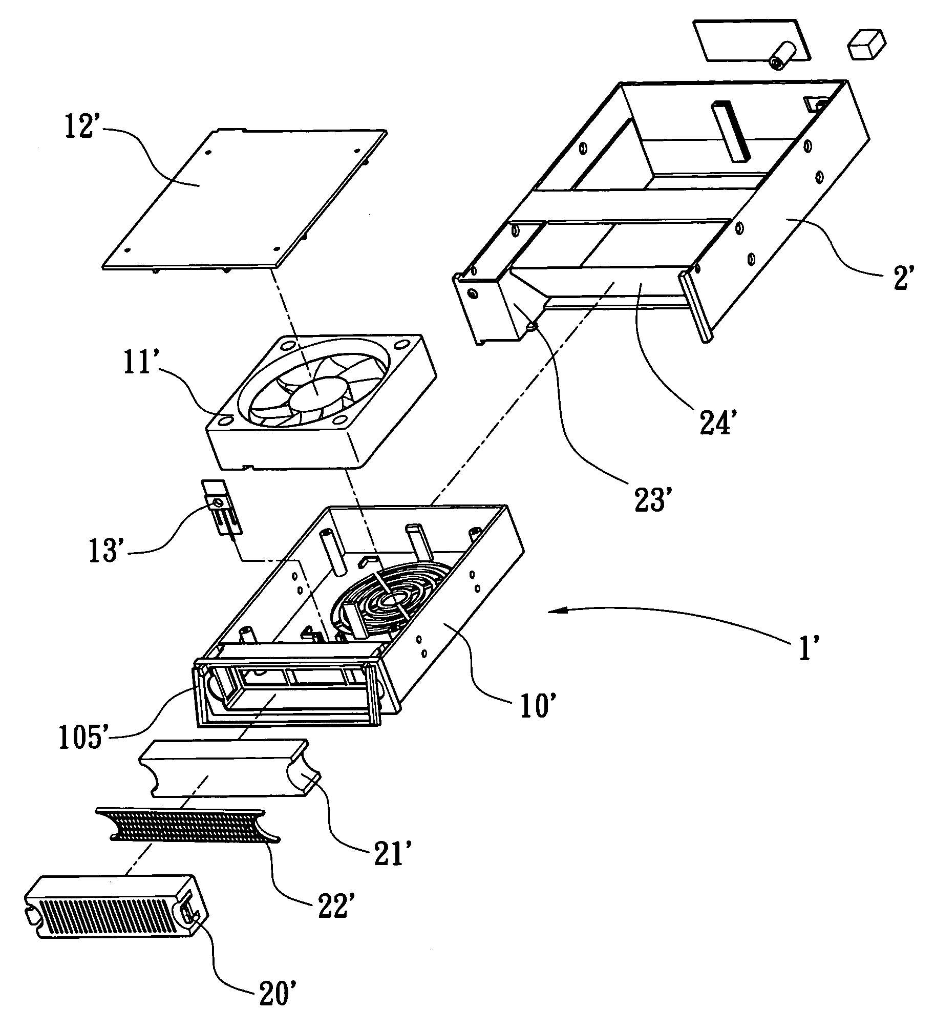
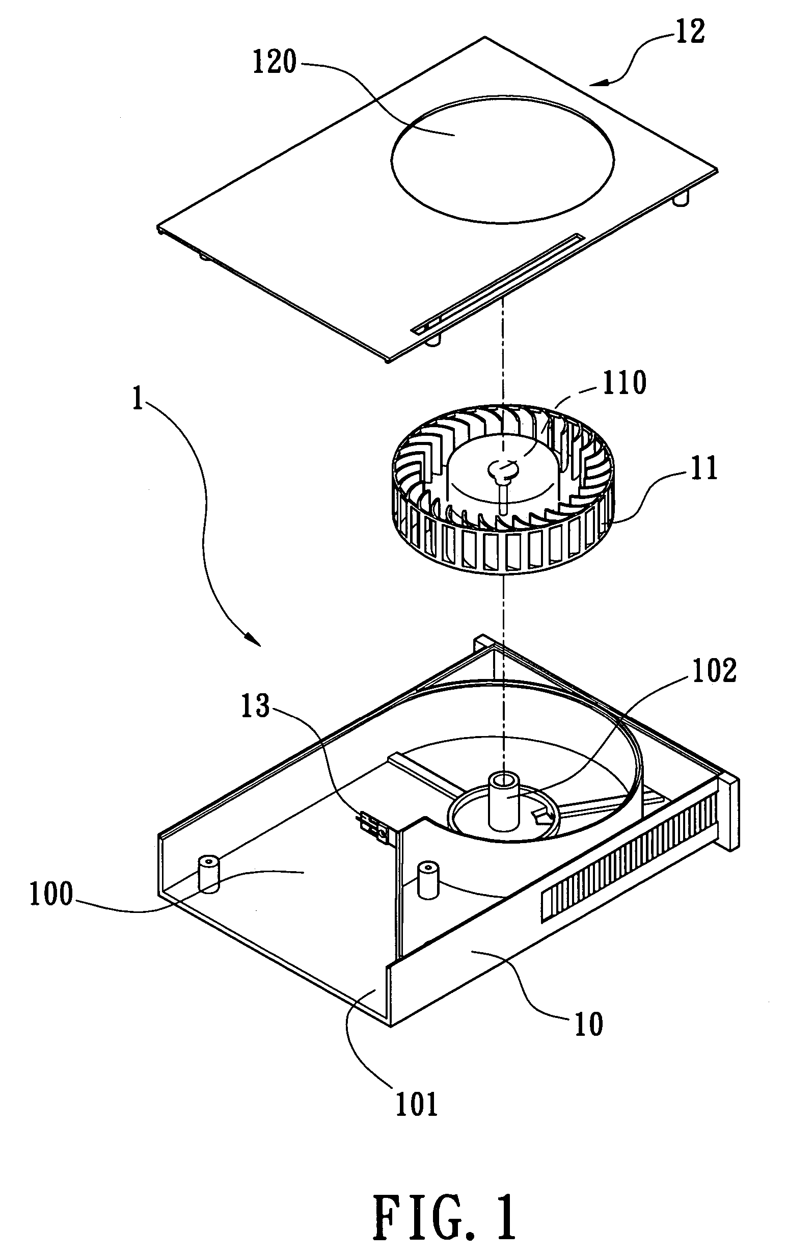
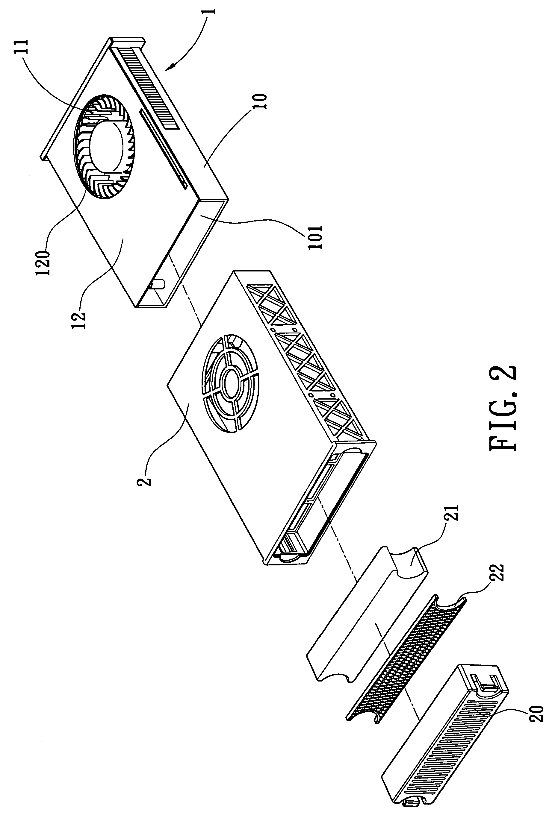
[0017]Additionally, FIG. 5 shows the present invention, a fan 11′ of a computer fan 1′ is a conventional axial-flow fan. Two fixing components 103′ are projective and disposed in a fan body 10′. The fan 11′ is disposed in the fan body 10′ and is locked between the two fixing components 103′. One face of the fan body 10′ is designed to be a detachable cover plate 12′ for convenient installation.

[0018]The fan body 10′ has an intake 101′ and an air vent 120′. An air passageway 100′ is formed between the intake 101′ and the fan 11′. The air vent 120′ is perpendicular to the air passageway 100′ and corresponds to the fan 11′. A positioning portion 104′ is disposed on said air passageway 100′ and used to install one or more UV LEDs 13′. A photo-catalytic net 21′ and a filter net 22′ are disposed on the intake 101′, so that the UV LED 13′ can fully illuminate the photo-catalytic net 21′. A ventilation panel 20′ whose shape and size matching the intake 101′ is dispose on the intake 101′.

[00...

fourth embodiment

[0020]FIG. 7 shows the present invention, wherein a computer 1″ comprises a ventilation panel 20″, a filter net 22″, a photo-catalytic net 21″, a connection frame 14″, a UV LED 13″, a bow-shaped holder 15″, three parallel arranged fans 11″ defining axial-flow fans and disposed in a shell body 16″. After the filter net 22″ and the photo-catalytic net 21′ are slipped into the ventilation panel 20″, they are then assembled in the connection frame 14″. The UV LED 13″ is installed on the bow-shaped holder 15″, which is fixedly disposed at the middle one of the fans 11″. The fans 11″ are received in the shell body 16″. The connection frame 14″ is locked onto the shell body 16″ by screws (not shown). When the connection frame 14″ is locked onto the shell body 16″, it is necessary to let the filter net 22″, the photo-catalytic net 21′ and the UV LED 13″ placed in the connection frame 14″ face one another so that the UV LED 13″ can fully illuminate the photo-catalytic net 21″. Additionally, ...


PUM


Abstract

A computer fan assembly mechanism having filtering and sterilizing functions comprises a fan body. An air passageway is formed at a hollow portion in the fan body. The air passageway has an intake and an air vent, which corresponds to the fan, is located on the fan body. A photo-catalytic net is disposed at the intake. One or more UV LEDs are disposed on the air passageway to illuminate the photo-catalytic net. Through illumination of the UV LED onto the photo-catalytic net, the object of filtering and sterilizing air passing the intake can be accomplished.

Description

FIELD OF THE INVENTION[0001]The present invention relates to a computer fan assembly mechanism having filtering and sterilizing functions and, more particularly, to a computer fan assembly mechanism making use of an ultraviolet (UV) LED to illuminate a photo-catalytic net for filtering and sterilizing air passing its intake.BACKGROUND OF THE INVENTION[0002]A conventional computer mainly uses an extractor fan located on its power supply for heat-radiation. The extractor fan starts to suck exterior air to the inside of the computer via a preset through hole on the computer. The air sucked in passes motherboard, hard disk, floppy disk, CPU, CD-ROM drive and so on, enters the power supply, and then is discharged out by the extractor fan. Although heat-radiating effect is accomplished, dust mites in air are also sucked into the computer and stay on various kinds of electronic components and the circuit. After accumulation for a long time, the heat-radiating effect of the circuit will be ...

Claims


Application Information

Patent Timeline
Patent Type & Authority Patents(United States)
IPC IPC(8): H05K7/20
CPCH05K7/20181G06F1/20
Inventor OU YANG, CHIEHOU YANG, WEI
Owner OU YANG CHIEH
Why Eureka
Try Eureka