Low-pass filtering device with integrated insulator and private installation comprising same
a filtering device and filtering technology, applied in the field of low-pass filtering devices with integrated insulators and private installations comprising same, can solve the problems of interference between -band signals and telephony, impairment of phonic quality, and impedance mismatch between tbe or nbts and private installations
- Summary
- Abstract
- Description
- Claims
- Application Information
AI Technical Summary
Benefits of technology
Problems solved by technology
Method used
Image
Examples
first embodiment
[0142]First Variant FIG. 8A:
[0143]The device comprises an isolator I with switching diodes D in opposite orientations and a low-pass filter F of order greater than 1.
[0144]The device can be produced by taking any type of low-pass filter LC of order greater than 1 or a different design.
[0145]It can be produced with different types of diodes and therefore by putting several diodes in series or by putting several diodes in parallel.[0146]In FIG. 8A the filter F is a second order LC filter (the references L correspond to inductors and C to capacitors).
[0147]Inductors can be placed between the IPC access and the isolator, and in this case either they replace the first series of inductors of the filter or they are added to this first series.
[0148]Second Variant FIG. 8B, as Produced:
[0149]Each switching diode of the 1N4148 type has a threshold voltage of approximately 0.6 V. The set of the series of 2×5 diodes in parallel therefore makes it possible to filter all signals with an amplitude ...
second embodiment
[0164]First Variant: FIG. 12
[0165]A first variant of this second mode is depicted in FIG. 12.
[0166]In this case, the device comprises: an isolator I consisting of a diode bridge P (switching diodes D) and d′ at least one relay R; and a second-order low-pass filter F comprising at least one capacitor C. The diode bridge P makes it possible to bias the current at the relay R:[0167]The relay R opens the circuit of the capacitor C of the second-order filter F of type LC when the terminal NBTn is on hook. The device Dn then behaves like a first-order filter.[0168]When the terminal NBTn is off hook, the relay R closes the circuit at the capacitor C of the second order filter LC. The device then behaves like a second-order filter.
[0169]In the example embodiment which has been made, capacitors Cp have been taken for the diode bridge of 1 microfarad. The diodes are 1N4148 diodes of 0.6 V. The inductances of the filters make 10 mH, and the capacitor C of the filter is of 14.7 nanofarads.
[0170...
third embodiment
[0180]A description will now be given of a third embodiment relating to the first and second embodiments. This is a possible option for each of these modes making it possible to resolve the following problem:
[0181]The variant embodiments presented include diodes (for example Schotky diodes, or Zener diodes, see FIGS. 8A, 8B, 9, 10, 11A, 11B, 12 and 13). It has been assumed up till now that such diodes have negligible residual capacitances (for example below 10 pF, or a few tens of pF). In reality, it is possible or even likely for the components used to have not insignificant residual capacitances.
[0182]In such a case, the device is therefore liable to have a minimum of impedance in the frequency band of the broad-band services. This would result in a reduction in their performance.
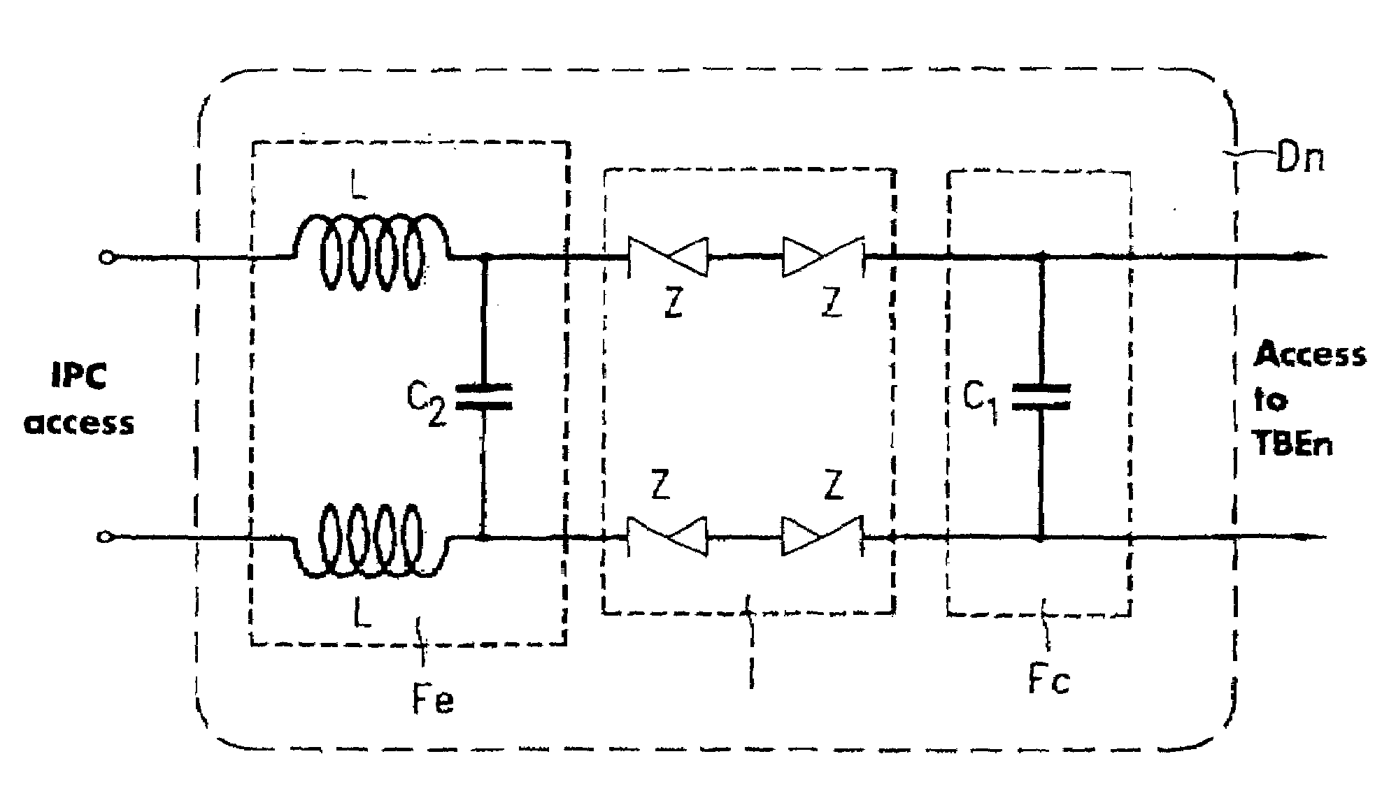
[0183]To resolve this problem, it has been proposed to place at the input of the device (on the IPC side) a first second-order LC filter of high impedance, referred to as the input filter Fe. The filterin...
PUM
 Abstract
Description
Claims
Application Information
 - R&D
- Intellectual Property
- Life Sciences
- Materials
- Tech Scout
- Unparalleled Data Quality
- Higher Quality Content
- 60% Fewer Hallucinations
Browse by: Latest US Patents, China's latest patents, Technical Efficacy Thesaurus, Application Domain, Technology Topic, Popular Technical Reports.
© 2025 PatSnap. All rights reserved.Legal|Privacy policy|Modern Slavery Act Transparency Statement|Sitemap|About US| Contact US: help@patsnap.com


