Process cartridge, mounting mechanism therefor and electrophotographic image forming apparatus

a technology of process cartridges and mounting mechanisms, applied in the direction of electrographic process apparatus, instruments, optics, etc., to achieve the effect of superior and operability regarding the mounting

Active Publication Date: 2005-12-27
CANON KK
View PDF9 Cites 154 Cited by
  • Summary
  • Abstract
  • Description
  • Claims
  • Application Information

AI Technical Summary

Benefits of technology

[0010]The primary object of the present invention is to provide a combination of a process cartridge, a mechanism for mounting a process cartridge into the image assembly of an electrophotographic image forming apparatus, and an electrophotographic image forming apparatus, which is superior, in operability regarding the mounting of a process cartridge into the main assembly, to that in accordance with the prior art.
[0011]Another object of the present invention is to provide a combination of a process cartridge, a mechanism for mounting a process cartridge into the image assembly of an electrophotographic image forming apparatus, and an electrophotographic image forming apparatus, which assures that a process cartridge is moved from the cartridge mounting position to the image formation position.

Problems solved by technology

Therefore, it is unnecessary for an operator to push the cartridge to the inward end of the main assembly when mounting the process cartridge into the main assembly.

Method used


Image

  • Process cartridge, mounting mechanism therefor and electrophotographic image forming apparatus
  • Process cartridge, mounting mechanism therefor and electrophotographic image forming apparatus
  • Process cartridge, mounting mechanism therefor and electrophotographic image forming apparatus

Examples


embodiment 1

(Embodiment 1)

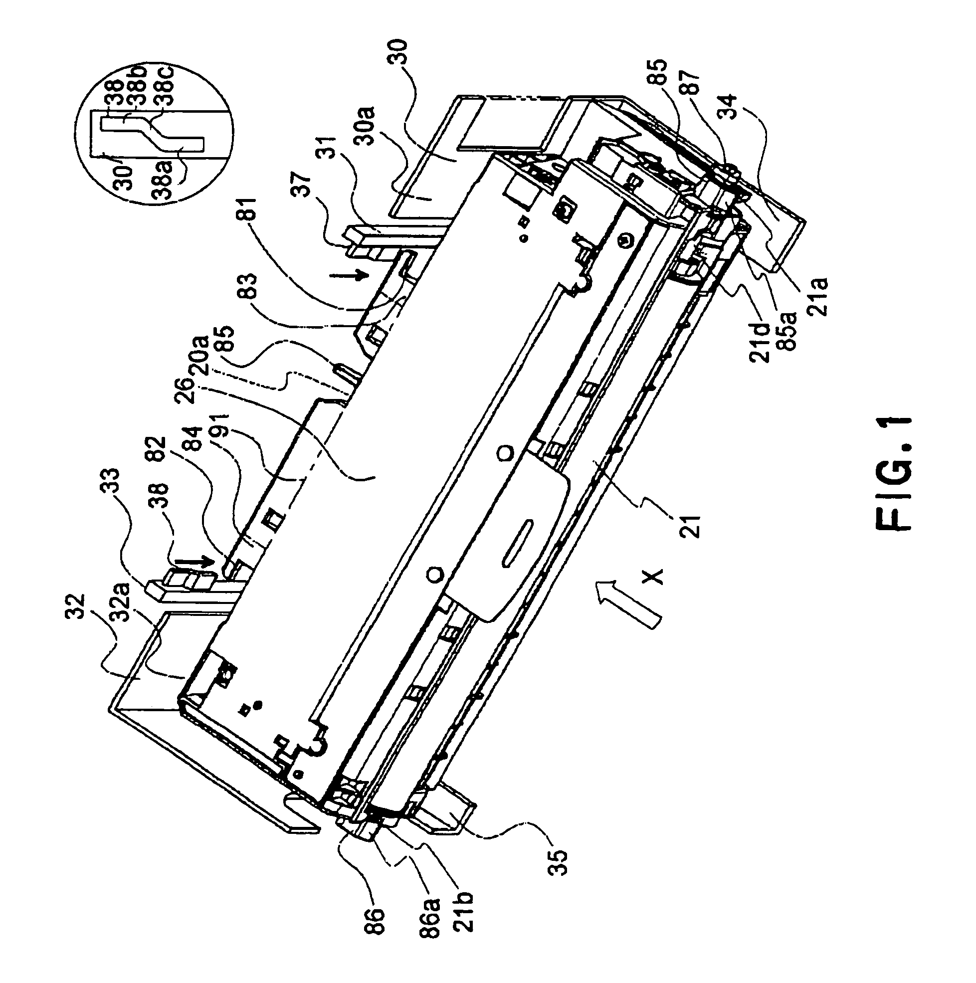
[0036]Hereafter, referring to FIGS. 1–12, the process cartridge and electrophotographic color image forming apparatus in the first embodiment will be described.

[Description of General Structure of Electrophotographic Color Image Forming Apparatus]

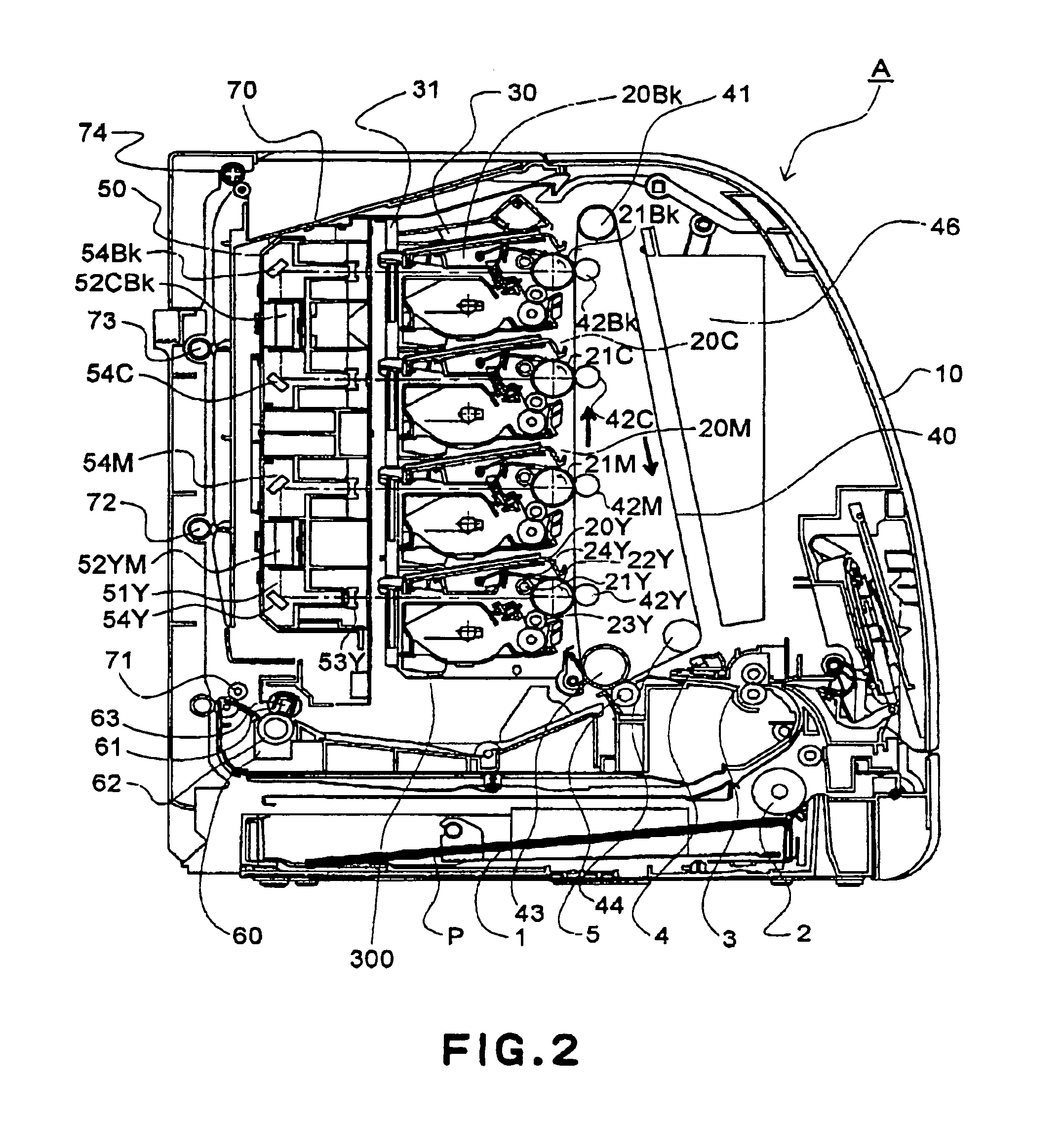
[0037]First, the general structure of the color image forming apparatus will be described with reference to FIG. 2, which is a sectional view of the image forming apparatus employing an electrophotographic process in this embodiment.

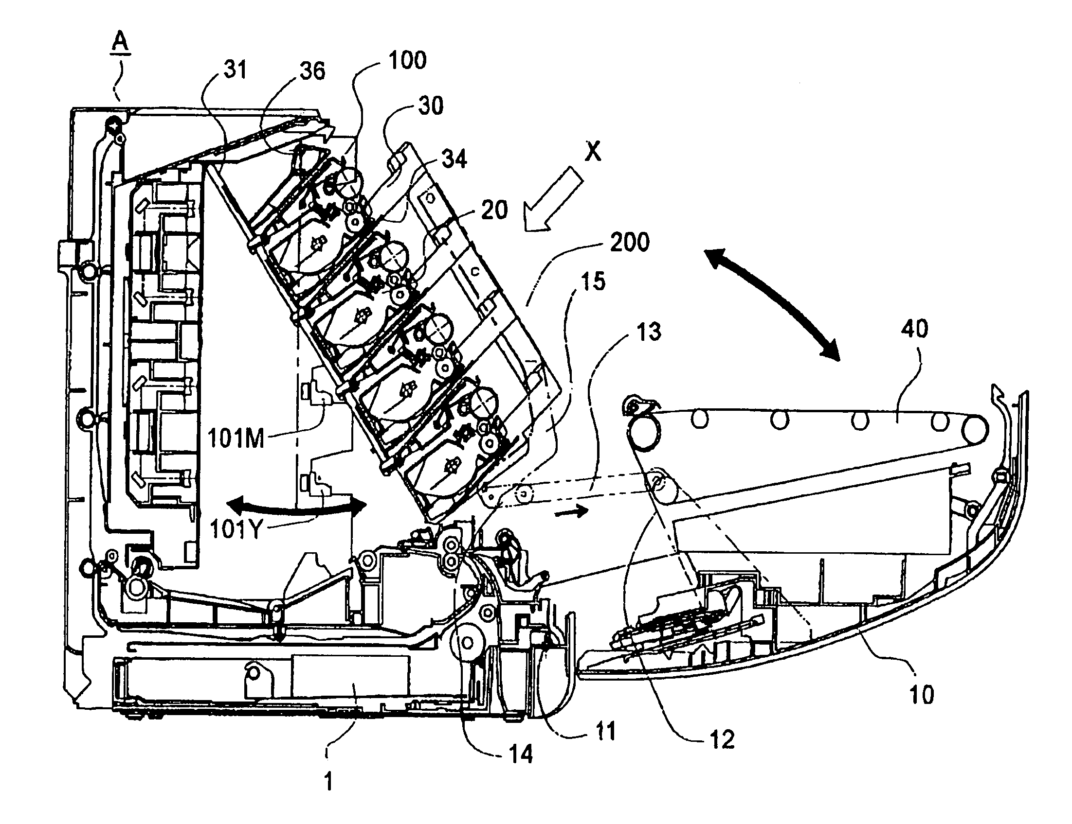
[0038]As shown in FIG. 2, the color laser printer A (which hereinafter will be simply referred to as “printer”) is a four-drum type (inline type) printer, which includes four process cartridges 20 (20Y, 20M, 20C, and 20Bk) and an intermediary transfer member (medium) 40.

[0039]The four process cartridges 20 (20Y, 20M, 20C, and 20Bk) are mounted in the main assembly of the color printer A, being vertically stacked. The cartridge 20Y stores developer of yellow color, and forms an image of the yellow d...

embodiment 2

(Embodiment 2)

[0172]Next, referring to FIGS. 4, and 13–18, the process cartridge and image forming apparatus in the second embodiment of the present invention will be described. The structures of the process cartridge and image forming apparatus similar to those in the first embodiment will not be described, and only those which characterize this embodiment will be described in detail.

[0173]FIG. 15 is a sectional view of the cartridge retaining member and its adjacencies in this embodiment, showing the positioning thereof. FIGS. 16, 17, and 18 are schematic sectional views of the cartridge retaining member in this embodiment.

[0174]Referring to FIG. 15, the reactive forces which act on the cartridge 20 are generated by the first cartridge retaining member 94 (94a, 94b, 94c, and 94d) on the side walls 100 and 110 of the apparatus main assembly A, and second cartridge retaining member 95 (95a, 95b, 95c, and 95d) on the intermediary transfer member 40 integral with the cover 10. Referri...


PUM


Abstract

A process cartridge which is capable of being carried on a movable guide provided in the main assembly of an electrophotographic image forming apparatus and which is movable from a receiving position toward a mount position in interrelation with movement of the movable guide, includes an electrophotographic photosensitive drum; process means actable on the drum; a cartridge frame supporting the drum and the process means; a first portion to be carried, provided at one longitudinal end of the drum, for being supported by the movable guide; a second portion to be carried, provided at the other longitudinal end of the drum, for being supported by the movable guide; a first positioning portion to be positioned relative to a main assembly, the first positioning portion extending outwardly from the cartridge frame adjacent the one longitudinal end of the drum; a second positioning portion to be positioned relative to the main assembly, the second positioning portion extending outwardly from the cartridge frame adjacent the other longitudinal end of the drum; and an engaging portion for engagement with a locking portion which is movable in interrelation with the movement of the movable guide to receive a pulling force for movement from the receiving position toward the mount position.

Description

FIELD OF THE INVENTION AND RELATED ART[0001]The present invention relates to a process cartridge, a mechanism for mounting a process cartridge, and an electrophotographic image forming apparatus.[0002]Here, an electrophotographic image forming apparatus refers to an apparatus which forms an image all recording medium (for example, recording paper, OHP sheet, fabric, etc.) with the use of one of the electrophotographic image forming methods. As examples of an electrophotographic image forming apparatus, there are an electrophotographic copying machine, an electrophotographic printer (for example, laser printer, LED printer, etc.) a facsimile machine, a word processor, as well as a complex machine (multi-function printer, etc.) comprising a combination of two or more of the preceding apparatuses.[0003]A process cartridge refers to a cartridge which is removably mountable in the main assembly of an image forming apparatus, and in which a charging means as a processing means, a developi...

Claims


Application Information

Patent Timeline
Patent Type & Authority Patents(United States)
IPC IPC(8): G03G21/18G03G15/00
CPCG03G21/1839G03G2221/1861G03G2221/1884G03G21/18
Inventor MURAYAMA, KAZUNARIYOKOMORI, KANJINITTANI, SUSUMUMAESHIMA, HIDEKI
Owner CANON KK
Why Eureka
Try Eureka