Yarn feeders of flat knitting machine

a flat knitting machine and feeder technology, applied in knitting, weft knitting, textiles and papermaking, etc., can solve the problems of increasing the weight of the yarn feeder and the size of the yarn feeder

Inactive Publication Date: 2006-01-03
SHIMA SEIKI MFG LTD
View PDF11 Cites 35 Cited by
  • Summary
  • Abstract
  • Description
  • Claims
  • Application Information

AI Technical Summary

Benefits of technology

[0012]To achieve the above object, yarn feeders for a flat sewing machine according to the present invention are characterized by being arranged such that feeder case portions are slidably engaged with a knitting yarn guide rail disposed at an upper portion of needle beds and can be selectively brought by a bringing device. Each feeder case is provided with a yarn feeding position and two waiting positions, i.e. a first waiting position and a second waiting position across the yarn feeding position for a yarn feeding port and with a switching mechanism for switching a yarn feeding port to the feeding position and the first and second waiting positions by swinging the yarn feeding port, characterized in that, of the two waiting positions of the yarn feeding port, the waiting position, which is located on an upper side relative to th

Problems solved by technology

Accordingly, when the yarn feeder 12a is at this position, a problem occurs in that knitting yarn extending in an obliquely lower right direction from the yarn feeder 12a is erroneously fed to a knitting needle for knitting in next knitting region B.
This problem of an increase in size of the yarn feeder also occurs in a yarn feeder disclosed in, for

Method used


Image

  • Yarn feeders of flat knitting machine
  • Yarn feeders of flat knitting machine
  • Yarn feeders of flat knitting machine

Examples


Embodiment Construction

[0026]An embodiment of a yarn feeder of a flat knitting machine of the present invention will be explained below based on the drawings.

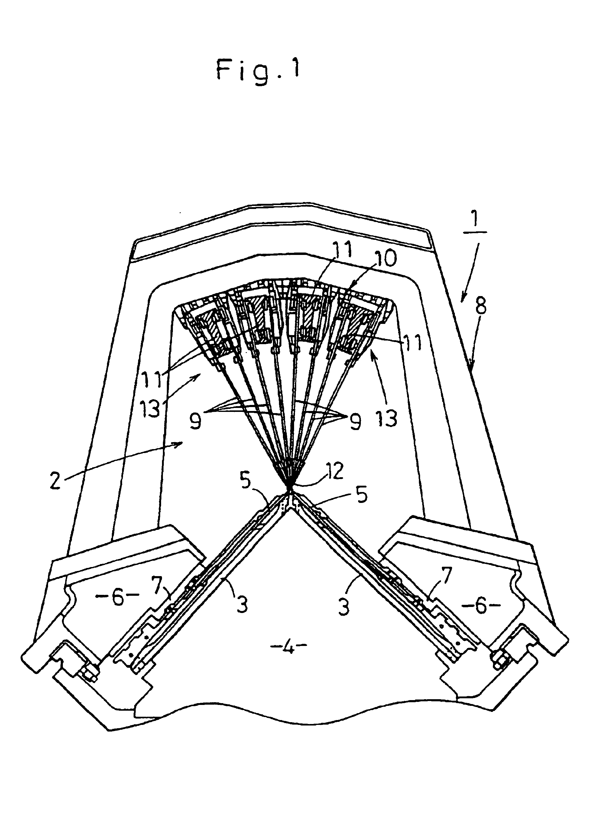
[0027]FIG. 1 is a side elevational view of a flat knitting machine having a yarn feeding apparatus including yarn feeders of the present invention, wherein reference numeral 1 denotes the flat knitting machine in its entirety, and 2 denotes the yarn feeding apparatus.

[0028]The flat knitting machine 1 has a pair of (front and back) needle beds 3 disposed on a frame 4 in a fan shape with extreme ends thereof confronting each other, and each needle bed 3 has plural knitting needles 5 disposed thereon in parallel with each other so that they are movable back and forth.

[0029]A carriage 6 is disposed on an upper surface of each needle bed 3 so that it can be caused to reciprocatingly travel by a belt drive device (not shown), and the knitting needles 5 are advanced and retreated by a knitting cam 7 attached to the carriages 6.

[0030]A gate arm 8 is disposed...


PUM


Abstract

Yarn feeders are arranged such that feeder case portions are slidably engaged with a knitting yarn guide rail disposed on an upper portion of needle beds, and can be selectively brought by a bringing device. Each of the feeder cases is provided with a switching mechanism for switching a yarn feeding port to a feeding position and a waiting position by swinging the port. The switching mechanism is operated at a time during which a yarn feeder selected by the bringing device is brought from a stop state in order to feed yarn. The yarn feeding port is switched from the waiting position to the feeding position, a swinging direction of the yarn feeding port to the waiting position, after it feeds yarn, is set, and the yarn feeding port can be switched from the feeding position to the waiting position in association with a selection cancel operation of the bringing device after the yarn is fed.

Description

TECHNICAL FIELD[0001]The present invention relates to yarn feeders for a flat knitting machine, and more particularly to yarn feeders used to knit an intersia pattern.BACKGROUND ART[0002]A fabric having an intersia pattern can be formed by knitting the fabric with different yarns by switching several yarn feeders, when one course is knitted, without separating the fabric.[0003]When the fabric having the intarsia pattern is knitted, as shown in FIG. 11, plural yarn feeders 12a and 12b are slidably disposed on a knitting yarn guide rail. The yarn feeder 12a feeds yarn to a first knitting region A, the yarn feeder 12b feeds yarn to a second knitting region B, and the yarn feeder 12a is replaced with the yarn feeder 12b at respective yarn changing point. However, when the yarn feeder 12a has fed yarn to a leftmost knitting needle of knitting needles for knitting in knitting region A from a right side, the yarn feeder 12a has already passed through a point P1 and is positioned leftward t...

Claims


Application Information

Patent Timeline
IPC IPC(8): D04B15/52D04B7/26D04B15/56
CPCD04B15/56D04B7/26
Inventor IKOMA, KENJI
Owner SHIMA SEIKI MFG LTD
Why Eureka
Try Eureka