Rear projection display device

a display device and rear projection technology, applied in the field of rear projection display devices, can solve problems such as image quality degradation, and achieve the effect of improving brightness and image quality

Inactive Publication Date: 2006-01-03
SANYO ELECTRIC CO LTD
View PDF25 Cites 33 Cited by
  • Summary
  • Abstract
  • Description
  • Claims
  • Application Information

AI Technical Summary

Benefits of technology

[0016]The present invention was made to solve the above problems and to provide a rear projection display device capable of improving brightness and image quality through the use of efficient image light that is projected onto a screen on a slant.
[0027]This structure ensures that a polarization direction of the green component from the image light synthesized by the color synthesizing means, is adjusted to be parallel to a horizontal cross section of the screen even when the polarization direction of the green light is not parallel to the horizontal cross section.

Problems solved by technology

Furthermore, the image quality is degraded because of the reflected light.

Method used


Image

  • Rear projection display device
  • Rear projection display device
  • Rear projection display device

Examples


Embodiment Construction

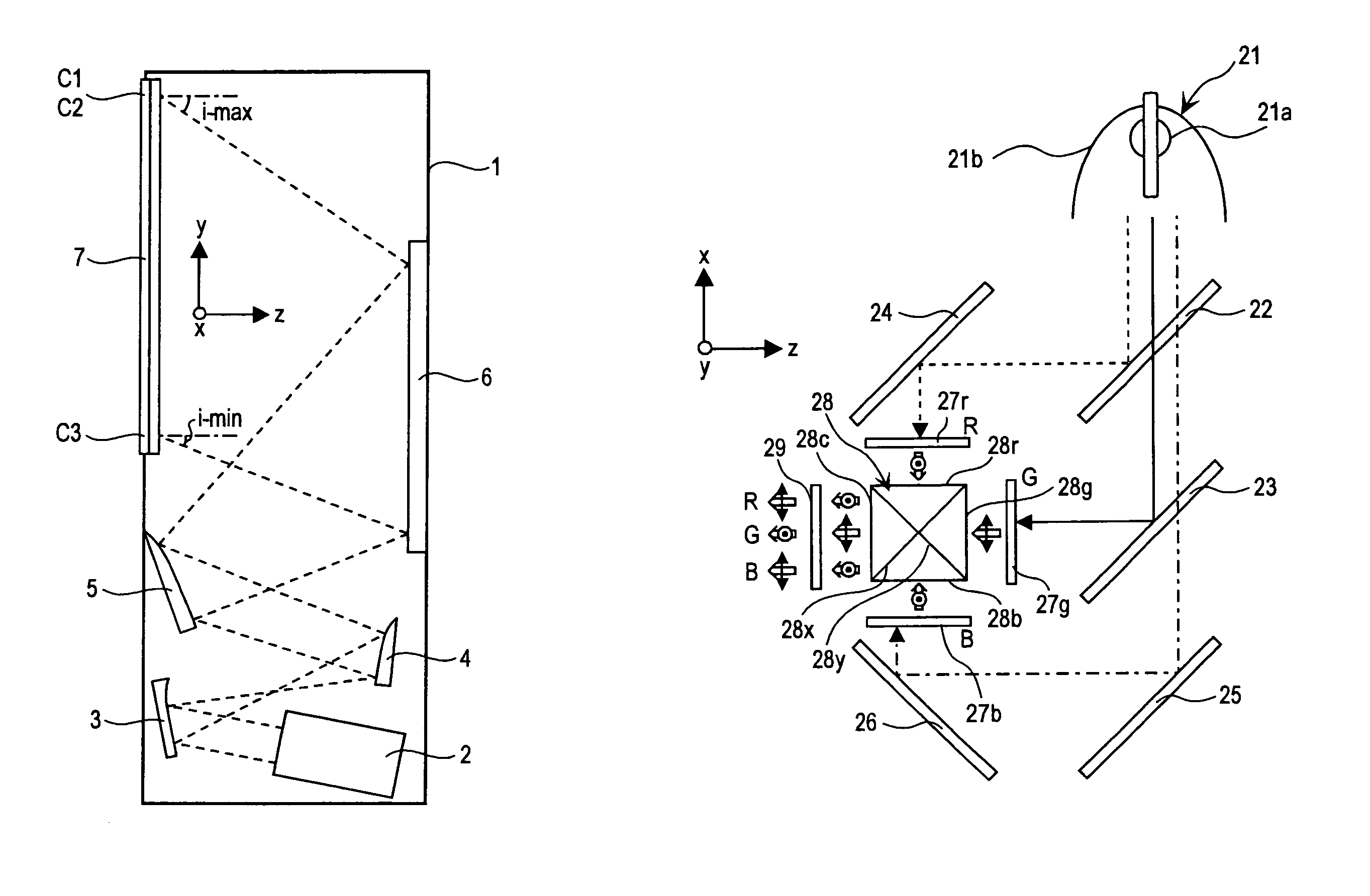
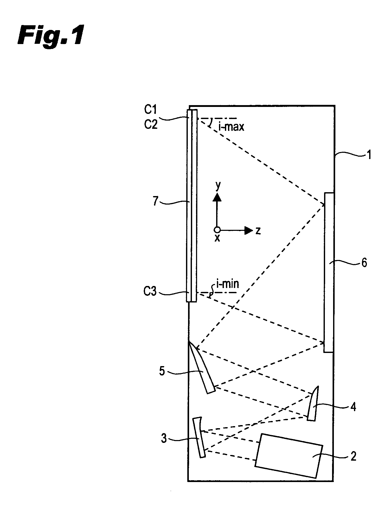
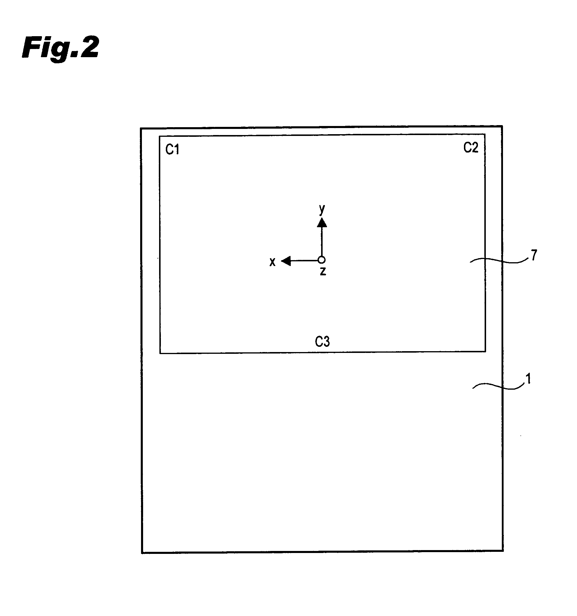
[0072]Explanation of one of the embodiments of a rear projection display device according to the present invention is made by referring to the drawings. In the following description, a coordinate system where a width direction of a rectangular screen 7 is taken along an x-axis, a height direction of the screen 7 is taken along a y-axis, and a perpendicular direction to the screen 7 is taken along a z-axis.

[0073]In this embodiment, FIG. 1 is a cross sectional view of the rear projection display device, and FIG. 2 is a front elevation of the device. FIGS. 3, 4 illustrate a structure of a projection unit in the rear projection display device of FIG. 1, wherein FIG. 3 is a top plan view, and FIG. 4 is a side view. FIG. 5 is an enlarged segmentary sectional view of a screen of the rear projection display device of FIG. 1. FIG. 6 is a graph of the reflectivity characteristic of light incident to acrylic resin from the air, and FIG. 7 is a graph of the reflectivity characteristic of light ...


PUM

PropertyMeasurementUnit
wavelengthaaaaaaaaaa
angleaaaaaaaaaa
angleaaaaaaaaaa

Abstract

A rear projection display device improves the brightness by improving the utilization efficiency of image light projected to a screen from slantly below. At least a green component of the image light is P-polarized to the screen (7). Therefore, reflection of light on the screen (7) is reduced.

Description

BACKGROUND OF THE INVENTION[0001]1. Field of the Invention[0002]This invention relates to a rear projection display device which enables an observer to observe a picture on a front surface of a screen by slanting projecting image light onto a back surface of a screen.[0003]2. Description of the Prior Art[0004]FIGS. 9, 10 illustrate one example of a conventional rear projection display device. Specifically, FIG. 9 illustrates a cross sectional view of a conventional rear projection display device, and FIG. 10 illustrates a top plan view of the rear projection display device shown in FIG. 9. In the following description, a coordinate system is used where a horizontal direction of a rectangle screen 170 is taken along an x-axis, a vertical direction of the screen 170 is taken along a y-axis, and a perpendicular direction to the screen 170 is taken along a z-axis.[0005]The rear projection display device of FIG. 9 includes: a projection unit 120 arranged in a body 110; a projection lens ...

Claims


Application Information

Patent Timeline
Patent Type & Authority Patents(United States)
IPC IPC(8): G03B21/22G02F1/1335G03B21/14G03B21/28G03B21/56G03B21/10
CPCG03B21/28G03B21/10
Inventor ARAI, KAZUHIROYOSHII, SYOICHI
Owner SANYO ELECTRIC CO LTD
Why Eureka
Try Eureka