Throwing wheel assembly

a technology of throwing blades and assemblies, which is applied in the direction of rotor blades, grinding/polishing apparatuses, manufacturing tools, etc., can solve the problems of not being able to quickly and easily remove and replace the blade elements, being exposed to significant abrasive contact, and commonly undergoing considerable wear and tear

Active Publication Date: 2006-01-03
BLAST CLEANING TECH INC
View PDF24 Cites 10 Cited by
  • Summary
  • Abstract
  • Description
  • Claims
  • Application Information

AI Technical Summary

Benefits of technology

[0012]The present invention satisfies the needs and alleviates the problems discussed above. In one aspect, there is provided an improved throwing wheel assembly including a rotatable wheel and a throwing blade removably positionable on a face of the rotatable wheel in a throwing position, the throwing blade having a holding structure projecting therefrom. The improvement comprises: (a) the face having a recess therein and (b) the throwing wheel assembly further comprising a retainer which is removably positionable in the recess and is adapted for removably receiving the holding structure such that the retainer will retain the throwing blade in the throwing position.
[0013]In another aspect, there is provided an improved throwing wheel assembly including a rotatable wheel having an axis of rotation and a plurality of throwing blades, each of the throwing blades being removably positionable on a face of the rotatable wheel in a throwing position and each of the throwing blades also having a holding structure projecting therefrom. The improvement comprises (a) the face having a recess therein extending around the axis of rotation and (b) the throwing wheel assembly further comprising a plurality of retainers removably positionable in the recess, each of the retainers being adapted to removably receive the holding structure of a corresponding one of the throwing blades such that the retainers will retain each of the throwing blades in the throwing position.

Problems solved by technology

Because of the action of the abrasive material within the centrifugal blasting apparatus, the throwing blades will commonly undergo considerable wear and must be replaced periodically.
Unfortunately, in order to provide a sufficiently secure attachment for the blasting operation, the blade attachment assemblies used heretofore typically have not allowed the blade elements to be quickly and easily removed and replaced.
Unfortunately, however, the lower detents 53 and / or the locking features 51 formed in the face 9 of wheel 13 for receiving and retaining the lower holding structure 26 of blades 14 are exposed to significant abrasive contact and can be highly susceptible to wear.

Method used


Image

  • Throwing wheel assembly
  • Throwing wheel assembly
  • Throwing wheel assembly

Examples


Embodiment Construction

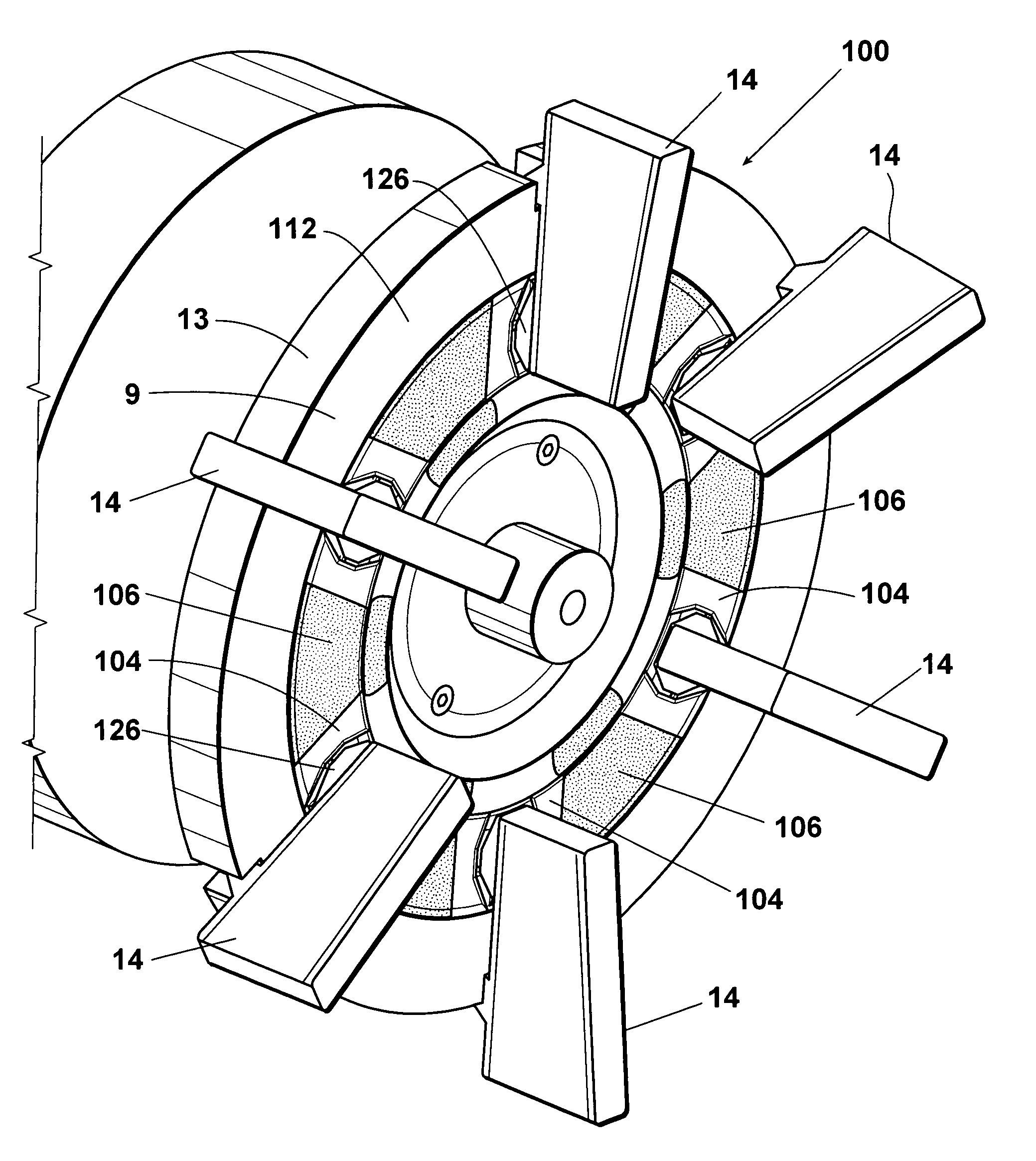
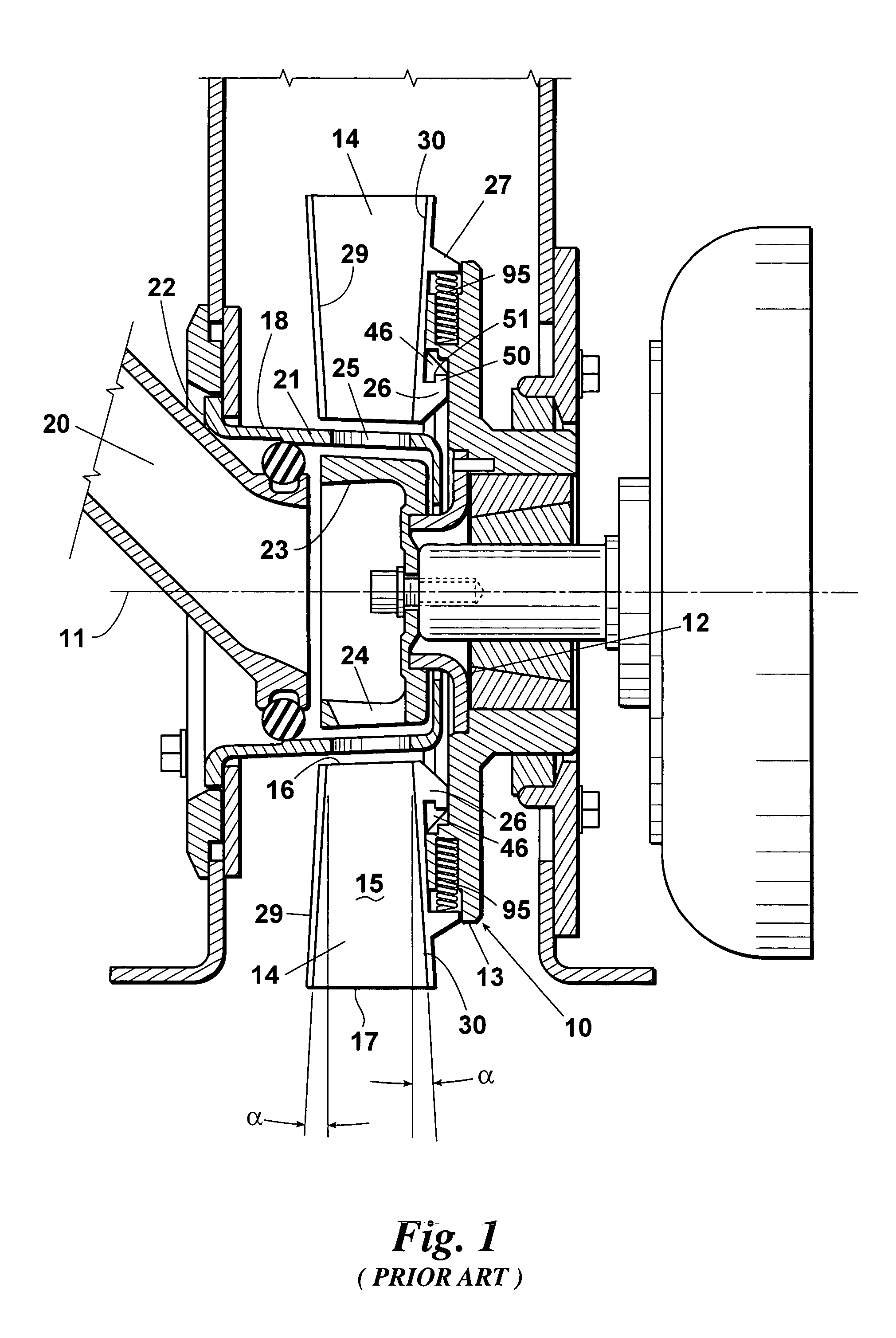
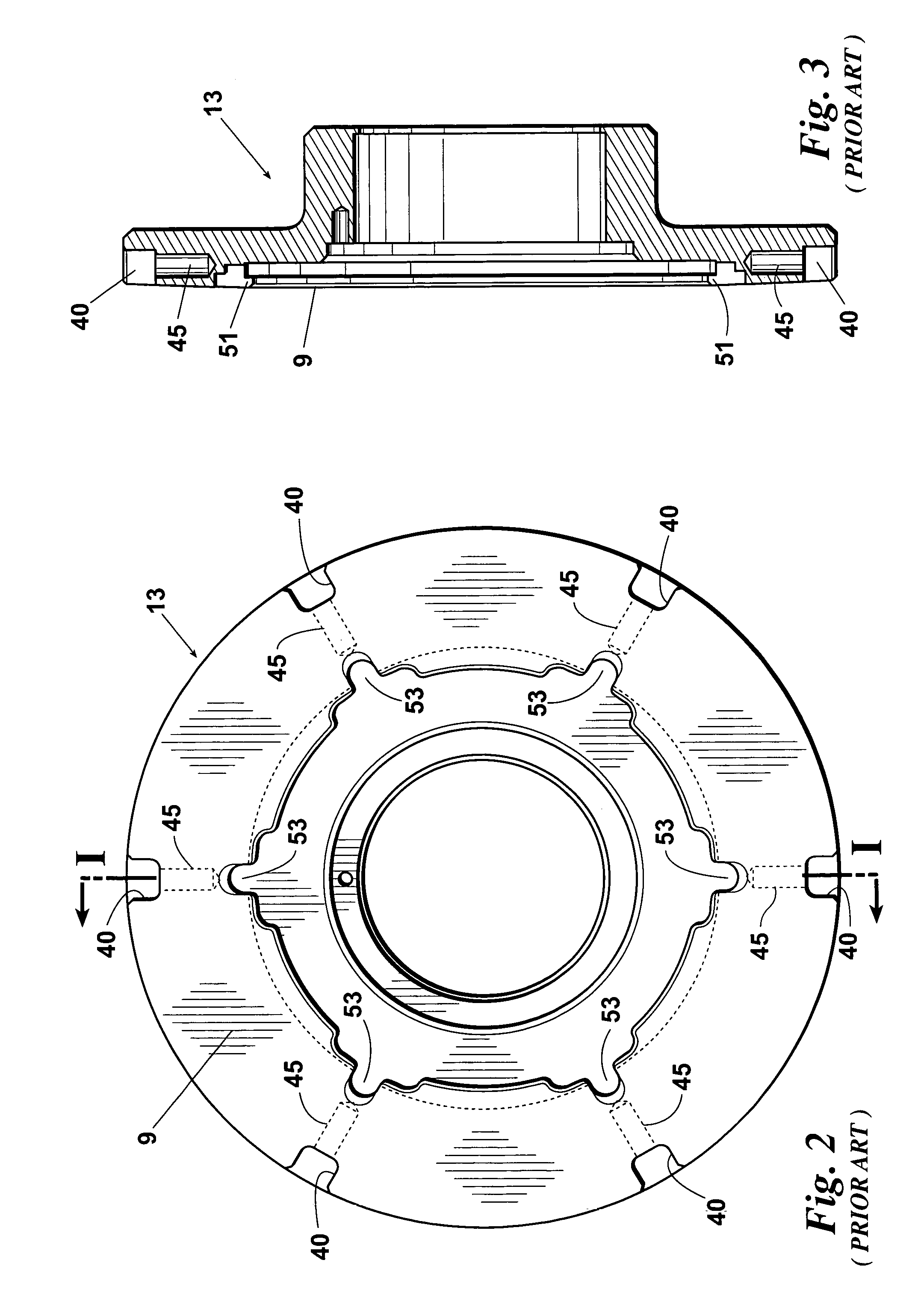
[0030]An embodiment 100 of the inventive improved throwing wheel assembly is depicted in FIGS. 5–15. The embodiment 100 of the improved inventive assembly is essentially identical to the prior art assembly 10 except that, rather than forming lower detents 53 and locking features 51 in the face 9 of the throwing wheel, the inventive improvement comprises: (a) a circular recess 102 which is formed in face 9 and extends around the axis of rotation 11 of throwing wheel 13 and (b) one or more retainers 104 which are removably secured in recess 102. If a plurality of retainers 104 are used, the improved throwing wheel assembly 100 can also optionally include one or more spacers 106 positioned in recess 102 between the retainers 104.

[0031]The embodiment 100 of the improved throwing wheel assembly shown in FIGS. 5 and 6 includes six retainers 104 and blades 14 with a corresponding number of spacers 106 positioned between the retainers 104 such that the retainers 104 and spacers 106 form a r...


PUM

PropertyMeasurementUnit
holding structureaaaaaaaaaa
axis of rotationaaaaaaaaaa
abrasiveaaaaaaaaaa

Abstract

A throwing wheel assembly including a rotatable wheel and one or more throwing blades each removably positionable on the face of the wheel in a throwing position, the throwing blades having holding structures projecting therefrom and the improvement comprising one or more retainers which are removably positionable in a recess provided in the wheel face and which and are adapted for removably receiving and retaining the blade holding structures.

Description

FIELD OF THE INVENTION[0001]The present invention relates to throwing wheel assemblies for blasting machines.BACKGROUND OF THE INVENTION[0002]Centrifugal blasting machines are commonly used in the art to strip or clean metal castings and other items. Centrifugal blasting machines typically employ a throwing wheel assembly comprising a plurality of throwing elements, referred to as throwing blades, mounted on the face of a rotator, runnerhead, or other rotatable wheel element. The throwing blades are adapted for receiving a stream of abrasive particulate material and throwing the particulate material radially outward from the wheel at an appropriate discharge point.[0003]Because of the action of the abrasive material within the centrifugal blasting apparatus, the throwing blades will commonly undergo considerable wear and must be replaced periodically. To avoid having to replace the entire throwing wheel assembly, the blades must be removably mounted on the throwing wheel. Unfortunat...

Claims


Application Information

Patent Timeline
Patent Type & Authority Patents(United States)
IPC IPC(8): B24C5/00B21J5/04B24C5/06B24C7/00
CPCB24C5/062
Inventor GOFF, JAMES R.
Owner BLAST CLEANING TECH INC
Why Eureka
Try Eureka