Controlled turbocharger with integrated bypass

a turbocharger and bypass technology, applied in the direction of engine controllers, combustion engines, machines/engines, etc., can solve the problems of increasing the overall size of the turbine casing and increasing the size, so as to achieve less hysteresis, greater control, and more response

Inactive Publication Date: 2006-01-10
BORGWARNER INC
View PDF8 Cites 68 Cited by
  • Summary
  • Abstract
  • Description
  • Claims
  • Application Information

AI Technical Summary

Benefits of technology

[0022]The present invention was made based upon the discovery that a rotary valve can be designed with less hysteresis, more response, greater ease of control, and via which not only flow to scroll passages, but also a bypass function, can be controlled.

Problems solved by technology

Since this control surface must perform an additional function, the control surface must be made wider, which (a) increases the size of the rotary valve and (b) requires placemen of the bypass outlet on the same plane as the first and second scroll passages, which may result in an increased overall size of the turbine casing.

Method used


Image

  • Controlled turbocharger with integrated bypass
  • Controlled turbocharger with integrated bypass
  • Controlled turbocharger with integrated bypass

Examples


first embodiment

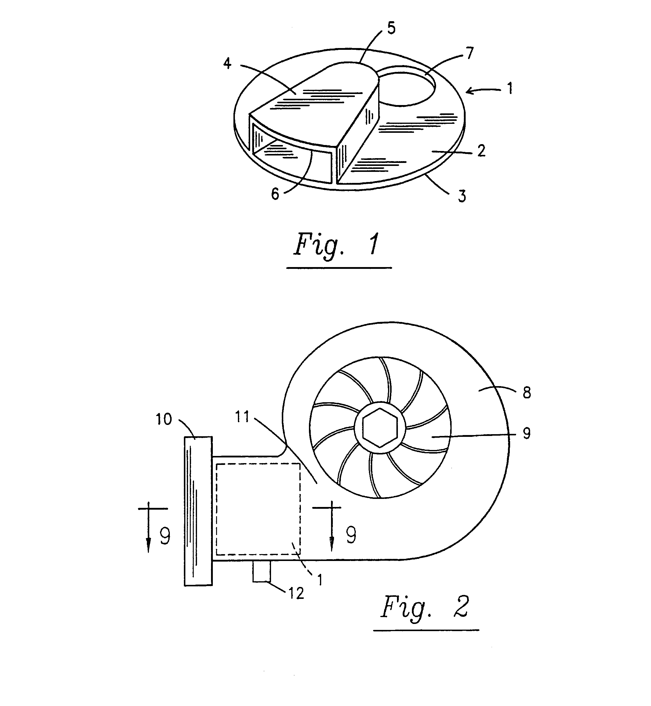
[0057]Turning now to the figures, FIG. 1 shows the rotary component 1 of the rotary valve for use in the invention. Base disk 2 is defined by a circular outer peripheral edge 3, and has an aperture 7 defined therein. Provided on one surface of the base disk is a control surface 4, shown in the figure as having a wedge shape with a blunted leading edge 5 and an arcuate trailing edge 6 concentric with the disk peripheral edge. The rotary valve axis of rotation passes behind the leading edge of the guide surface.

[0058]FIG. 2 shows the placement of the rotary guide valve within a generic turbine housing 8. The rotary valve 1 is provided in the turbine throat 11 downstream of a mounting flange 10 and upstream of the turbine wheel 9. The rotary valve is mounted for rotation about shaft 12.

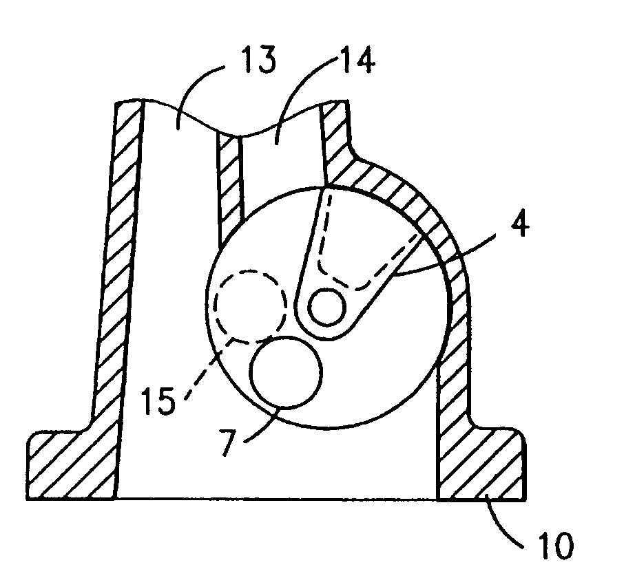
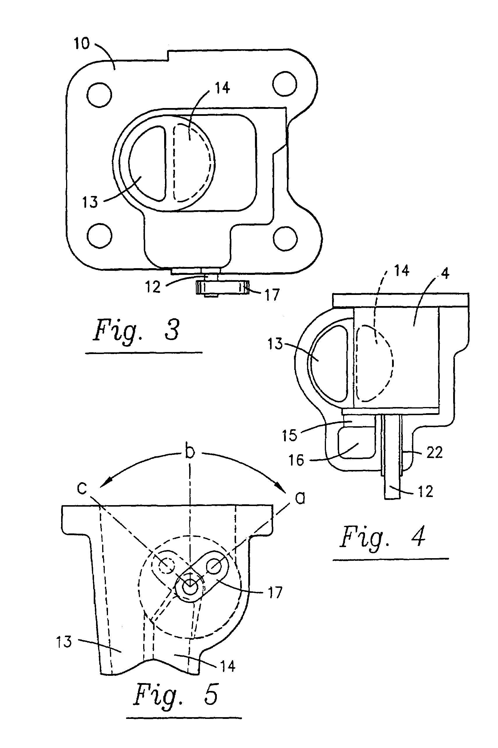
[0059]FIG. 3 is a view looking onto the mounting flange of the turbocharger, from which an outer (generally but not necessarily smaller) spiral 13 and inner (generally larger) spiral 14 can be seen, as w...

second embodiment

[0067]FIGS. 8 and 9 represent side and top cross-sectional views of the invention, with exhaust gas bypass channel arranged beside the rotary valve rather than below the rotary valve. The advantage of such a design is that the rotary valve is “flatter and wider” which may be desired in certain engine compartments. The rotary valve shaft is again mounted via a single bearing 22. The rotary valve can be easily accessed by removal of a lid part. In the rotary valve position shown in FIG. 9, the inner scroll14 and bypass channel 16 are blocked. By rotating the rotary valve clockwise, first inner scroll 14 becomes open, and upon further rotation bypass channel 16 becomes open.

[0068]A preferred embodiment of the invention is shown in FIG. 10. Here, the bypass channel is not positioned below the first and second flow channels, but is positioned on the other side of the valve shaft (as shown in the figure) from the inner and outer scrolls.

[0069]A further alternation in FIG. 10 is that the r...


PUM


Abstract

A rotary valve (1) particularly suitable for use in a turbocharger for an internal-combustion engine, the rotary valve provided between a turbocharger inlet port (10) and at least first and second scroll passages (13, 14), the rotary valve rotatable between (a) a position at which at least one scroll passage is blocked and a bypass outlet is blocked, (b) a position at which no scroll passage is blocked and the bypass outlet is blocked, and (c) a position at which no scroll passage is blocked and the bypass outlet is not blocked. The control valve is rotatable about a central axis, includes a disk-shaped base (2) and a control surface (4) provided upon said base, the control surface preferably being generally wedge shaped, and the disk optionally having an aperture (7) for communication with the bypass outlet. The rotary valve is preferably mounted on both sides via a shaft (112a, 112b) extending through the axis of rotation.

Description

CROSS REFERENCE TO RELATED APPLICATION[0001]This application is a national stage of PCT / US01 / 46323 filed Nov. 2, 2001 under the International Convention.BACKGROUND OF THE INVENTION[0002]1. Field of the Invention[0003]The invention relates to a compact controlled twin-flow or dual-flow turbocharger, preferably twin-flow, having an integrated bypass. The invention more particularly concerns a turbocharger with an improved rotary valve design for regulating gas flow, including bypass.[0004]2. Description of the Related Art[0005]Reciprocating internal combustion engines have long been equipped with turbochargers. In a simple uncontrolled fixed-nozzle turbocharger system, the maximum charging pressure is a function of the strength of the engine. The uncontrolled turbocharger must thus be so designed that the optimal performance is reached only at high engine speeds. Unfortunately, at all other speed regions the turbocharger provides suboptimal boost or air volume.[0006]Controlled turboch...

Claims


Application Information

Patent Timeline
Patent Type & Authority Patents(United States)
IPC IPC(8): F02D23/00F02B37/18F02B37/22
CPCF02B37/025F02B37/22F02B37/183Y02T10/144Y02T10/12
Inventor FRANKENSTEIN, DIRKMCKINLEY, STEVE
Owner BORGWARNER INC
Why Eureka
Try Eureka