
Offshore cargo rack for use in transferring palletized loads between a marine vessel and an offshore platform

a technology for offshore platforms and palletized loads, applied in the field of cargo racks, can solve the problems of huge storage problem of supplies on offshore oil well drilling or production platforms, and the volume of supplies transported is enormous

Inactive Publication Date: 2006-01-10
NESS DANNY
View PDF19 Cites 53 Cited by
  • Summary
  • Abstract
  • Description
  • Claims
  • Application Information

AI Technical Summary

Benefits of technology

The cargo rack system enhances the efficiency of cargo handling by allowing multiple pallets to be securely transported and stored on offshore platforms, optimizing space usage and preventing pollution through effective spill management, while enabling easy loading and unloading with forklifts and cranes.

Problems solved by technology

Drilling and production require that an enormous amount of supplies be transported from land based storage facilities.
The storage of supplies on an offshore oil well drilling or production platform is a huge problem.

Method used


Image

  • Offshore cargo rack for use in transferring palletized loads between a marine vessel and an offshore platform
  • Offshore cargo rack for use in transferring palletized loads between a marine vessel and an offshore platform
  • Offshore cargo rack for use in transferring palletized loads between a marine vessel and an offshore platform

Examples


Embodiment Construction

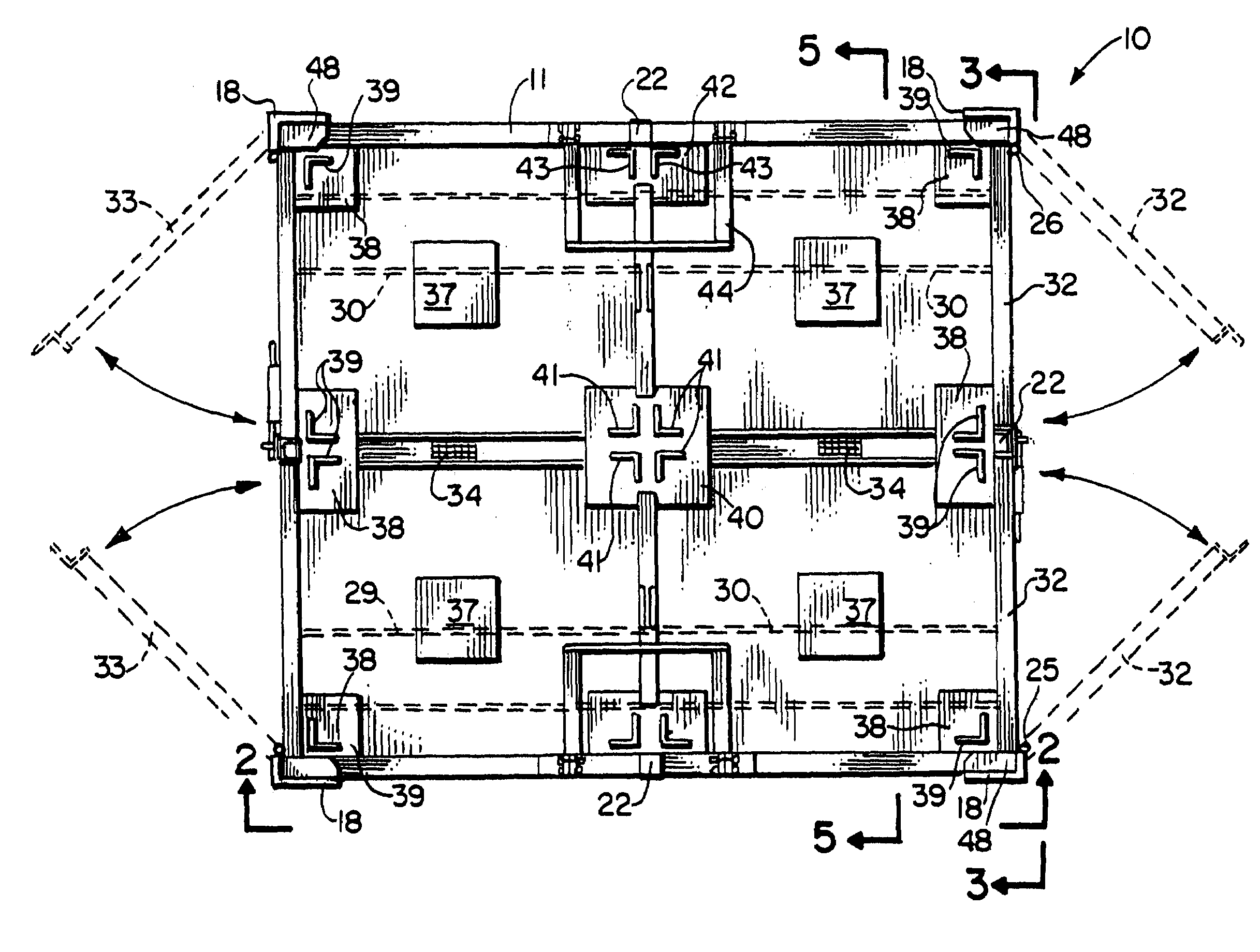
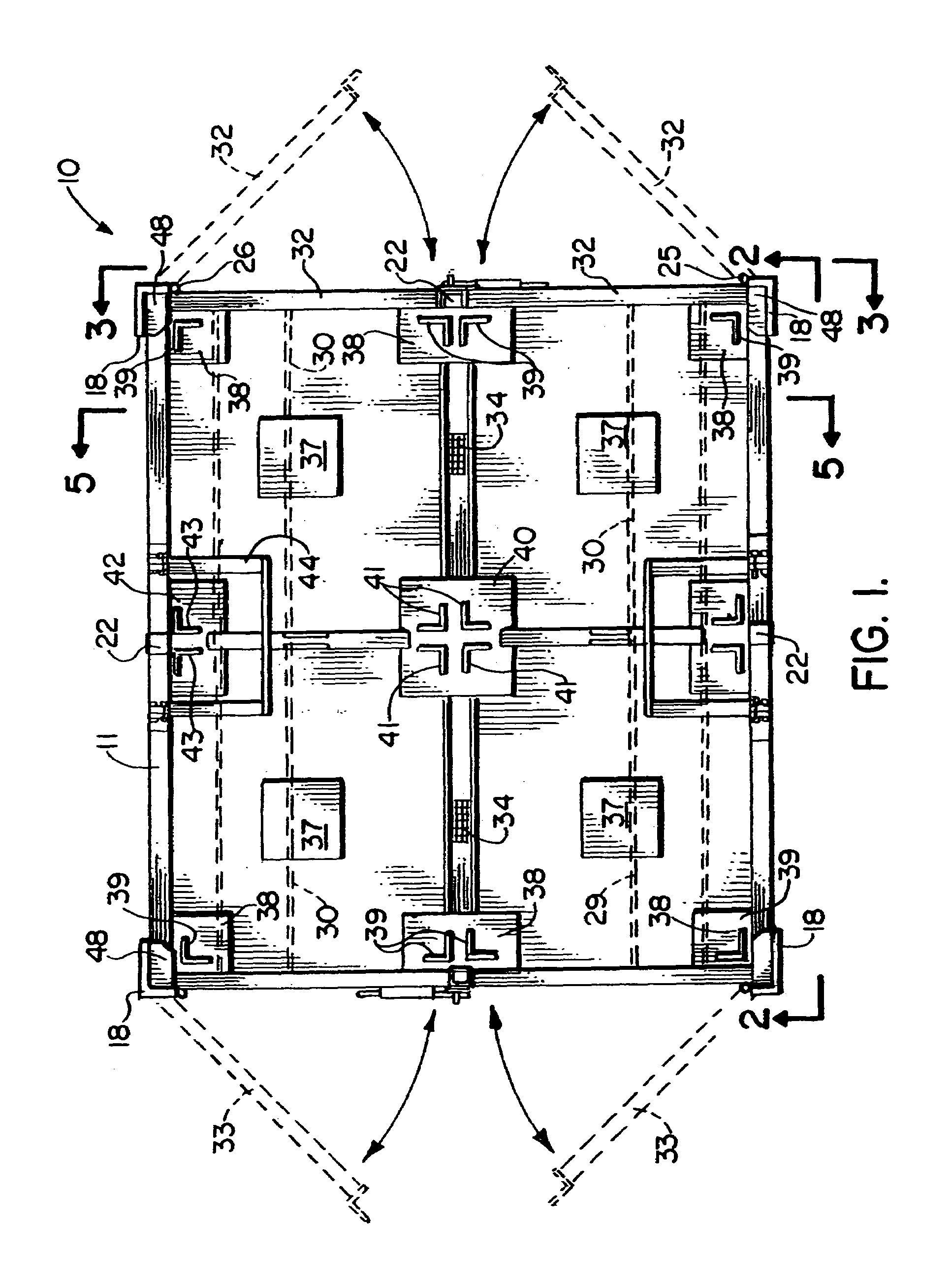
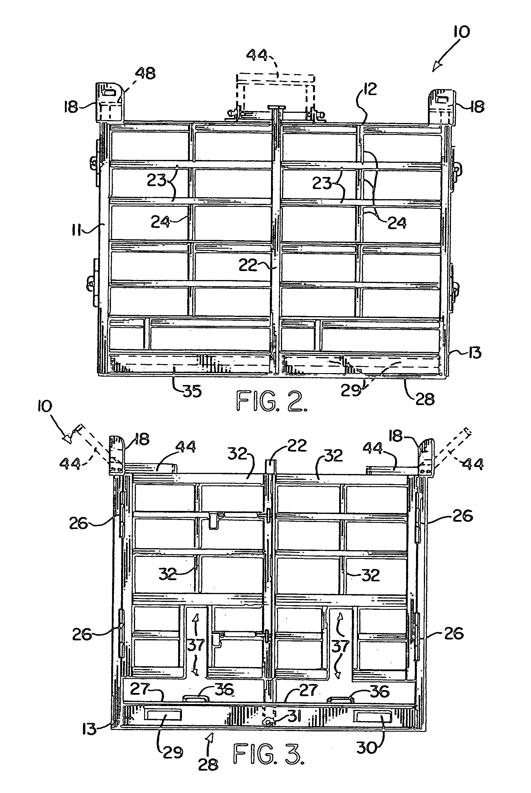
[0027]FIGS. 1–6 show the preferred embodiment of the apparatus of the present invention designated generally by the numeral 10. An alternate embodiment 10A is shown in FIG. 7. The preferred embodiment 10 is configured to hold four loads 60, 61, 62, 63. The alternate embodiment 10A is configured to hold two loads 60, 61. The loads can be palletized loads such as, for example, pallets attached with sacks of drilling mud.

[0028]Cargo rack 10 provides a frame 11 having an upper end portion 12 and a lower end portion 13. The frame 11 includes four corner columns 14, 15, 16, 17. A lifting eye fitting 18 is fitted (for example, welded) to the top of each corner column 14–17 as shown on the drawings. For lifting rack 10 or 10A with a crane, rigging can be attached to each lifting eye fitting 18. Rigging can be for example slings 20 and shackles 21 as shown. Rigging can include spreader bars. Such rigging 19 enables the entire cargo rack 10 and its cargo to be lifted using the rigging 19 and ...


PUM

PropertyMeasurementUnit
lengthaaaaaaaaaa
perimeteraaaaaaaaaa
movementaaaaaaaaaa

Abstract

A cargo rack for transferring loads between a marine vessel and an offshore marine platform (for example, oil and gas well drilling or production platform) provides a frame having a front, a rear, and upper and lower end portions. The lower end of the frame has a perimeter beam base, a raised floor and a pair of open-ended parallel fork tine tubes or sockets that communicate with the perimeter beam at the front and rear of the frame, preferably being structurally connected (e.g., welded) thereto. Openings in the perimeter beam base align with the forklift tine tubes or sockets. The frame includes a plurality of fixed side walls extending upwardly from the perimeter beam that include at least left and right side walls. A plurality of gates are movably mounted on the frame including a gate at least at the front and at least at the rear of the frame, each gate being movable between open and closed positions, the gates enabling a forklift to place loads on the floor by accessing either the front of the frame or the rear of the frame. Each gate can be pivotally attached to a fixed side wall. The frame has vertically extending positioning beams or lugs that segment the raised floor into a plurality of load-holding positions. Each load holding position has a plurality of positioning beams or lugs that laterally hold a load module (e.g., palletized load) in position once a load is placed on the raised floor.

Description

CROSS-REFERENCE TO RELATED APPLICATIONS[0001]Not applicableSTATEMENT REGARDING FEDERALLY SPONSORED RESEARCH OR DEVELOPMENT[0002]Not applicableREFERENCE TO A “MICROFICHE APPENDIX”[0003]Not applicableBACKGROUND OF THE INVENTION[0004]1. Field of the Invention[0005]The present invention relates to cargo racks for transferring goods between marine vessels and offshore platforms such as oil and gas well drilling and production platforms. More particularly, the present invention relates to an improved cargo rack that enables a user to load the rack with multiple palletized loads (or other loads) and to then transport the entire rack using a lifting device such as a crane or a forklift from the marine vessel to the platform. Additionally, the entire rack can be moved on land or on the platform with a crane or forklift.[0006]2. General Background[0007]In the exploration of oil and gas in a marine environment, fixed, semi submersible, jack up, and other offshore marine platforms are used duri...

Claims


Application Information

Patent Timeline
Patent Type & Authority Patents(United States)
IPC IPC(8): B65D19/44E21B21/01
CPCE21B21/01B65D19/44Y10T29/49826Y10T137/474Y10T137/4673B65D19/06B65D2519/008B65F1/1615
Inventor NESS, DANNY
Owner NESS DANNY
Learn More