Adjustable keyboard with adjusting and locking mechanism, and method of its use

a locking mechanism and adjustable technology, applied in the field of adjustable keyboards, can solve the problems of user discomfort, ulnar deviation, user stress, etc., and achieve the effects of convenient adjustment for users, easy manufacture and assembly, and low cos

Inactive Publication Date: 2006-01-10
KEY OVATION
View PDF11 Cites 26 Cited by
  • Summary
  • Abstract
  • Description
  • Claims
  • Application Information

AI Technical Summary

Benefits of technology

[0008]It is the object of the present invention to overcome or substantially ameliorate the disadvantages of the prior art. It is therefore an object of the present invention to provide an adjustable keyboard which is inexpensive and simple to manufacture, is made of few parts and parts which are easy to manufacture and assemble, and which is easy for the user to adjust to a large number of positions.
[0009]There is disclosed a keyboard having a plurality of keys, the keyboard having at least two segments which are mutually movable relative to one another, and wherein each segment of the keyboard includes some of the keys. Typically, the keyboard has at least two mutually pivotable segments which are attached to one another at a top end of the keyboard segments by way of a hinge or joint, such that a front edge of the keyboard may spread apart in at least a substantially horizontal plane, to thereby reduce ulnar deviation in the keyboard user. Advantageously, the hinge or joint is adapted to allow pivoting in both horizontal and vertical planes such that the two segments of the keyboard may reside in different planes, so that the center of the keyboard is raised to reduce pronation and therefore decrease tension in the wrists and forearms of the user.
[0010]The hinge or joint may preferably be composed of a ball and socket joint which includes a locking mechanism. The locking mechanism may be fashioned using a pivoting handle, in the form of a lever, which includes a cam. The cam may be used to force bearing surfaces against a ball on a ball element, to thereby frictionally retain the ball and socket joint in a fixed position. Upon pivoting of the handle away from the keyboard, the cam may release the ball from the friction fit with the bearing surfaces, thereby allowing the ball to slide in the socket, and therefore allowing the keyboard segments to be adjusted relative to one another.

Problems solved by technology

It is a disadvantage of such known keyboards that the wrists and / or arms and shoulders of an operator must be contorted into a configuration which is stressful to the user after prolonged use of the keyboard.
This problem is brought about by the fact that the hands of the user must be turned outwardly by pivoting of the wrists relative to the forearms, resulting in ulnar deviation.
Discomfort to the user caused by pronation of the wrists is also a problem with these known keyboards.
However, in each of the keyboards described in those patents, the locking mechanism includes a large number of parts.
As a result, those keyboards can be difficult to manufacture and assemble and therefore can be expensive, and those keyboards can be difficult for the user to adjust and lock.

Method used


Image

  • Adjustable keyboard with adjusting and locking mechanism, and method of its use
  • Adjustable keyboard with adjusting and locking mechanism, and method of its use
  • Adjustable keyboard with adjusting and locking mechanism, and method of its use

Examples


Embodiment Construction

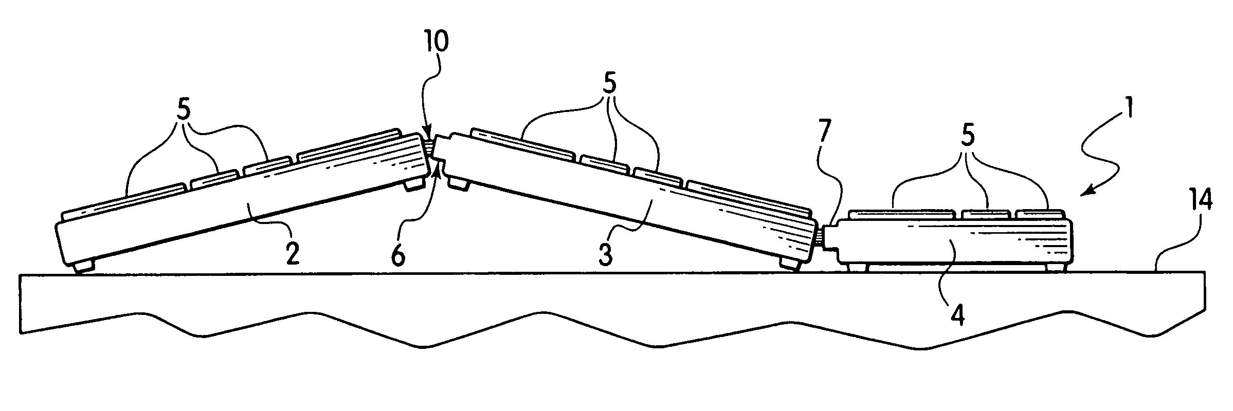
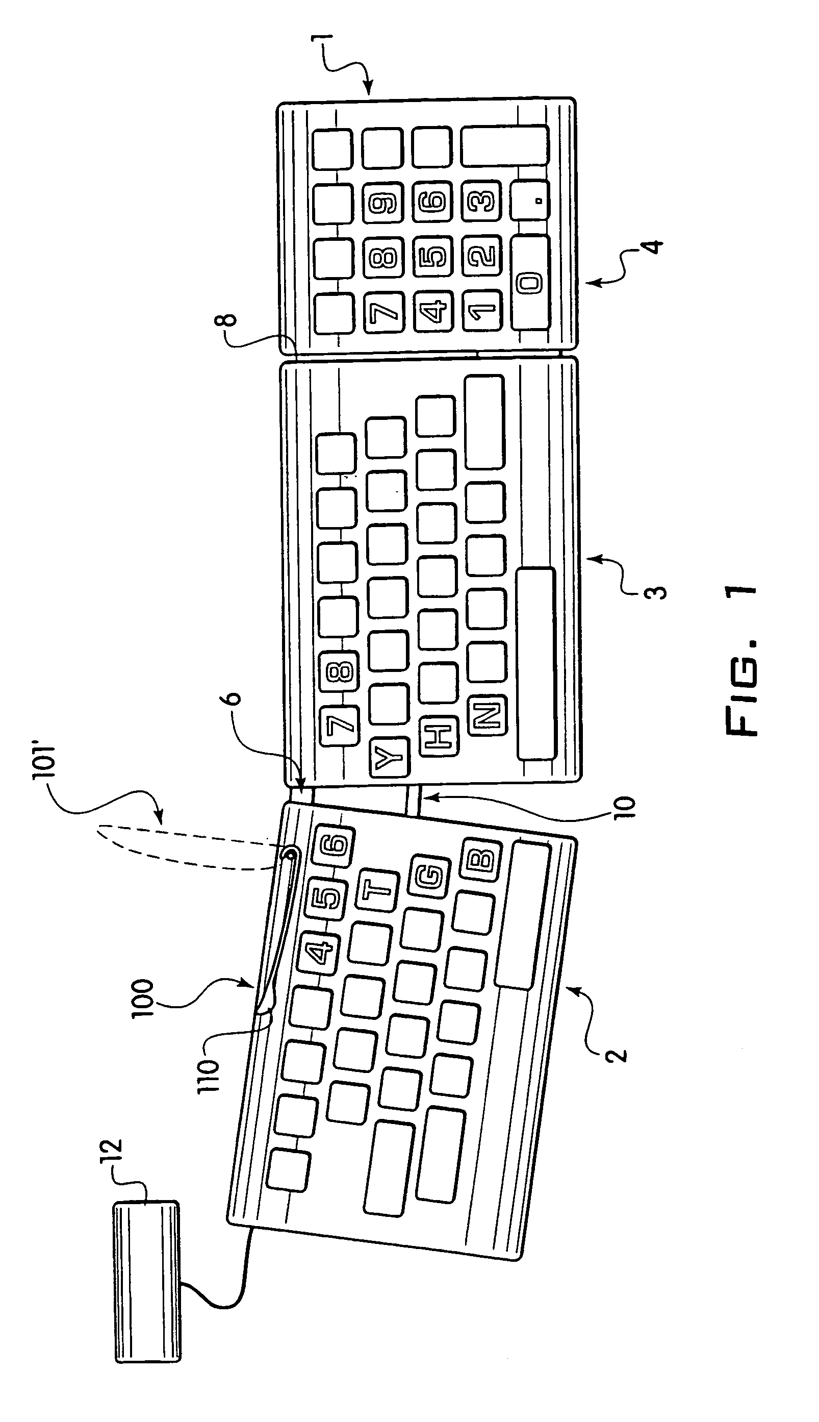
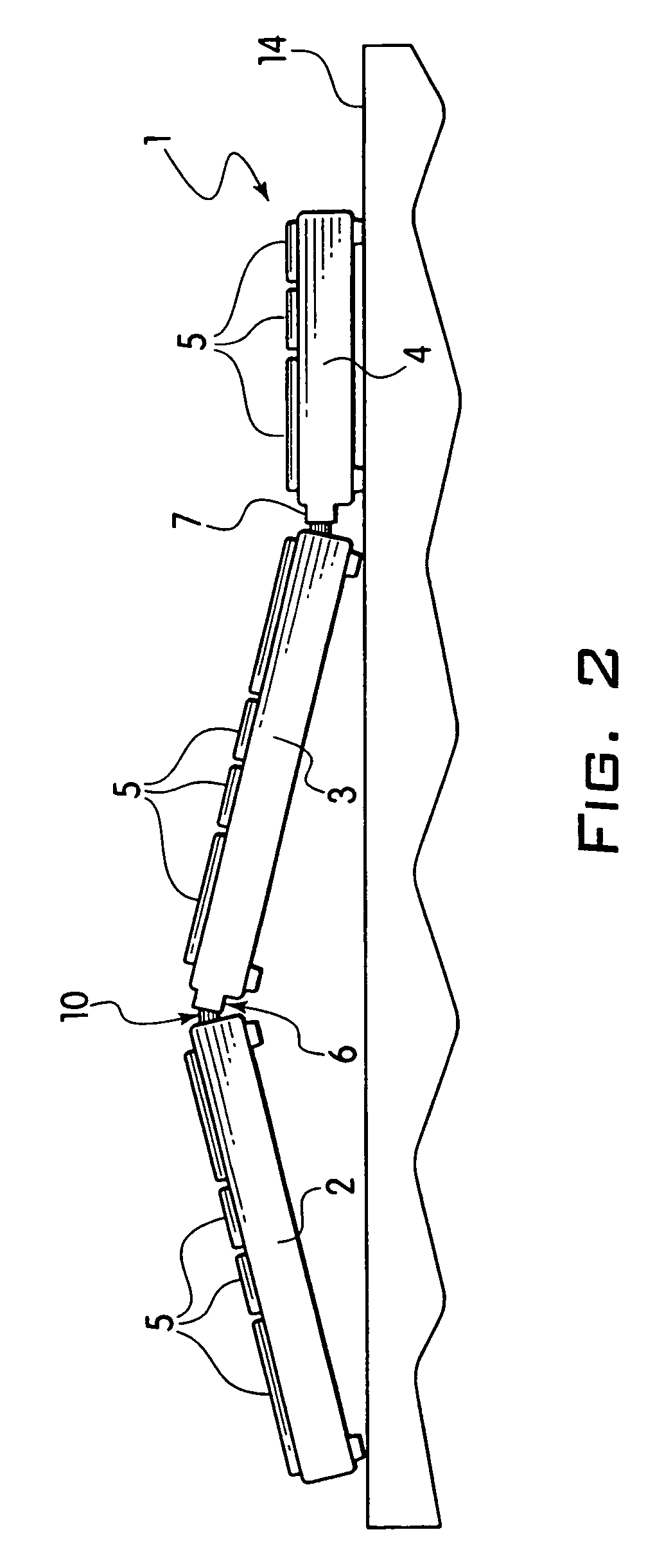
[0021]The present invention relates to a keyboard 1 to be used, for example, at a computer terminal 12. In the accompanying drawings there is schematically depicted a keyboard generally indicated by reference numeral 1. Keyboard 1 includes separate segments 2, 3, and 4, each having a plurality of keys 5. It is to be understood that the configuration of the keys on segments 2, 3, and 4, may be in any suitable form which allows access to the appropriate hand corresponding to segments 2, 3, and 4, and need not be the configuration shown in FIG. 1.

[0022]Segments 2 and 3 of keyboard 1 are usually attached by a hinge or joint 6, which may provide on e or more degrees of freedom of relative movement between segments 2 and 3. Hinge or joint 6 in the preferred embodiments is described in more detail below. As described in more detail below, a handle 100, in the form of a lever, forms a portion of a keyboard locking mechanism. The handle 100 may be pivoted from a locked position, which fixes ...


PUM


Abstract

The invention relates to an adjustable keyboard to be used, for example, at a computer terminal (12). The preferred embodiment is in the form of a keyboard having a number of keys (5), the keyboard being formed in at least two segments (2, 3) which are mutually movable relative- to one another using a hinge or joint (6). Each of the segments (2, 3) of the keyboard has mounted thereon some of the keys (5). The relatively movable nature of the keyboard aims at reducing stress and discomfort to the user by eliminating contortion to the user's wrists. More particularly, discomfort to the user caused by pronation of the wrists and / or ulnar deviation of the wrists is reduced. The hinge or joint (6) may be in the form of a ball and socket-type joint with a locking mechanism, which preferably includes a pivoted handle (100), in the form of a lever, used for locking and unlocking the hinge or joint (6).

Description

[0001]This application is a continuation-in-part of Application Ser. No. 09 / 384,700, filed Aug. 27, 1999, now U.S. Pat. No. 6,641,316.BACKGROUND OF THE INVENTION[0002]1. Field of the Invention[0003]The following invention relates to keyboards, and more particularly to a keyboard formed in two or more mutually pivotable segments which may be adjusted and locked into a number of different ergonomic positions.[0004]2. Description of the Prior Art[0005]Known keyboards of the type used at a computer terminal, for example, generally include a unitary board onto which alphanumeric keys are attached. It is a disadvantage of such known keyboards that the wrists and / or arms and shoulders of an operator must be contorted into a configuration which is stressful to the user after prolonged use of the keyboard. This problem is brought about by the fact that the hands of the user must be turned outwardly by pivoting of the wrists relative to the forearms, resulting in ulnar deviation. Discomfort t...

Claims


Application Information

Patent Timeline
Patent Type & Authority Patents(United States)
IPC IPC(8): B41J5/10G06F3/02
CPCG06F3/0216Y10T403/32311
Inventor GOLDSTEIN, MARK R.SKOSKIEWICZ, ANDREZEJJUE, CLIFFORDLAW, DAVID JOHN
Owner KEY OVATION
Why Eureka
Try Eureka