Liquid feed device for use on endoscopes

a technology of liquid feed device and endoscope, which is applied in the direction of mechanical equipment, applications, couplings, etc., can solve the problems of damage to the valve member, the check valve provided on the side of the liquid feed device becomes an obstacle in the washing operation, and the supply of cleaning and disinfectant liquid becomes an obstacle, so as to prevent spontaneous rotation, reduce the number of turns, and prevent the effect of rotational movemen

Inactive Publication Date: 2006-01-10
FUJI PHOTO OPTICAL CO LTD
View PDF3 Cites 27 Cited by
  • Summary
  • Abstract
  • Description
  • Claims
  • Application Information

AI Technical Summary

Benefits of technology

[0015]For fixing the liquid feed adaptor to the mouth piece at the liquid feed port, the nut member on the liquid feed adaptor is adapted to be threaded on an external male screw portion which is provided on the outer periphery of the mouth piece. In this case, preferably multiple thread screws are employed for the male and female screw portions on the mouth piece and the nut member, so that the liquid feed adaptor can be securely fastened to the mouth piece by a reduced number of turns. The casing of the manipulating head assembly of the endoscope is arranged to circumvent and cover up the male screw portion on the outer periphery of the mouth piece which would otherwise be exposed to the outside.
[0016]The nut member is rotatable relative to the Luer-Lok member but assembled in such a manner as to prevent its separation from the Luer-Lok member. More particularly, for this purpose, the flange portion which is provided at the outer proximal end of the Luer-Lok member serves as a stopper on one side. On the other hand, the above-mentioned stopper ring on the Luer-Lok member prevents dislocation of the nut member in the forward direction. The stopper ring can be fixed to the Luer-Lok member by various methods. In this regard, the stopper ring can be threaded onto the outer periphery of the Luer-Lok member and then bonded to the latter by the use of an adhesive. Further, when the liquid feed adaptor is fitted on the mouth piece at the liquid feed port, it is necessary to prevent spontaneous rotational movements of the liquid feed adaptor and the stopper ring. For this purpose, rotational movements of the liquid feed adaptor and the stopper ring can be blocked, for example, by engaging axial projections and notched grooves which are provided on meeting end faces of the stopper ring and the mouth piece or vice versa. In a case where fore ends of the axial projections are rounded off into an arcuate shape, the axial projections are automatically guided into position for engagement with the notched grooves in an assured manner.

Problems solved by technology

However, the check valve which is provided on the side of a liquid feed device becomes an obstacle in a washing operation, more specifically, an obstacle to the supply of cleaning and disinfectant liquids in a washing operation or to the insertion of a cleaning brush in a scrubbing operation.
In a case where a valve member is detachably fitted in a liquid feed passage as in the above-mentioned Japanese patent, there is a problem of damages to the valve member, caused by a hooking jig which is necessarily used at the time of forcibly mounting or dismantling the valve member into or out of the liquid feed passage.
On the other hand, in a case where a check valve is built in a passage forming member to be threaded into a mouth piece of a liquid feeder, the existence of the female screw on the inner periphery of the mouth piece makes it difficult to connect a syringe of a cleaning liquid or a disinfectant for washing the liquid feed passage up to the liquid injection port at the distal end of the insertion tube.

Method used


Image

  • Liquid feed device for use on endoscopes
  • Liquid feed device for use on endoscopes
  • Liquid feed device for use on endoscopes

Examples


Embodiment Construction

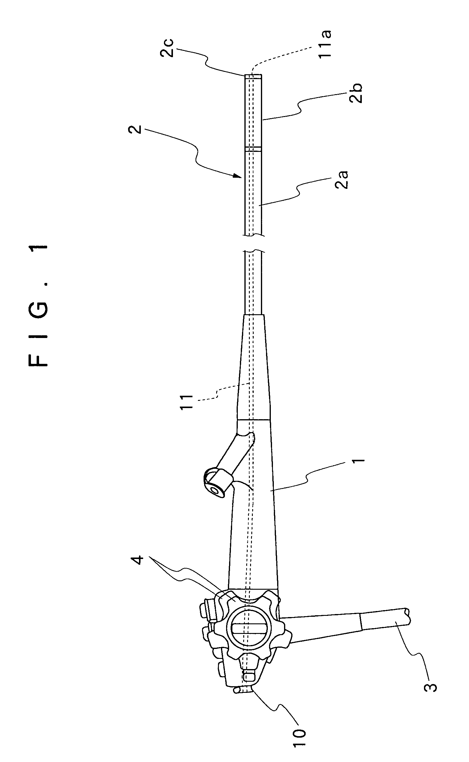
[0026]Hereafter, the present invention is described more particularly by way of its preferred embodiment with reference to the accompanying drawings. Firstly, referring to FIG. 1, there is schematically shown general layout of a flexible endoscope to which the present invention is applicable. In that figure, indicated at 1 is a manipulating head assembly of the endoscope, at 2 an insertion tube to be introduced into a body cavity, and at 3 a universal cable. The insertion tube 2 includes an elongated flexible portion 2a, an angle section 2b and a rigid tip end section 2c. For turning the rigid tip end section 2c into a desired direction, the angle section 2b can be bent in an arbitrary direction by manipulation of an angulation control means 4 which is provided on the manipulating head assembly 1.

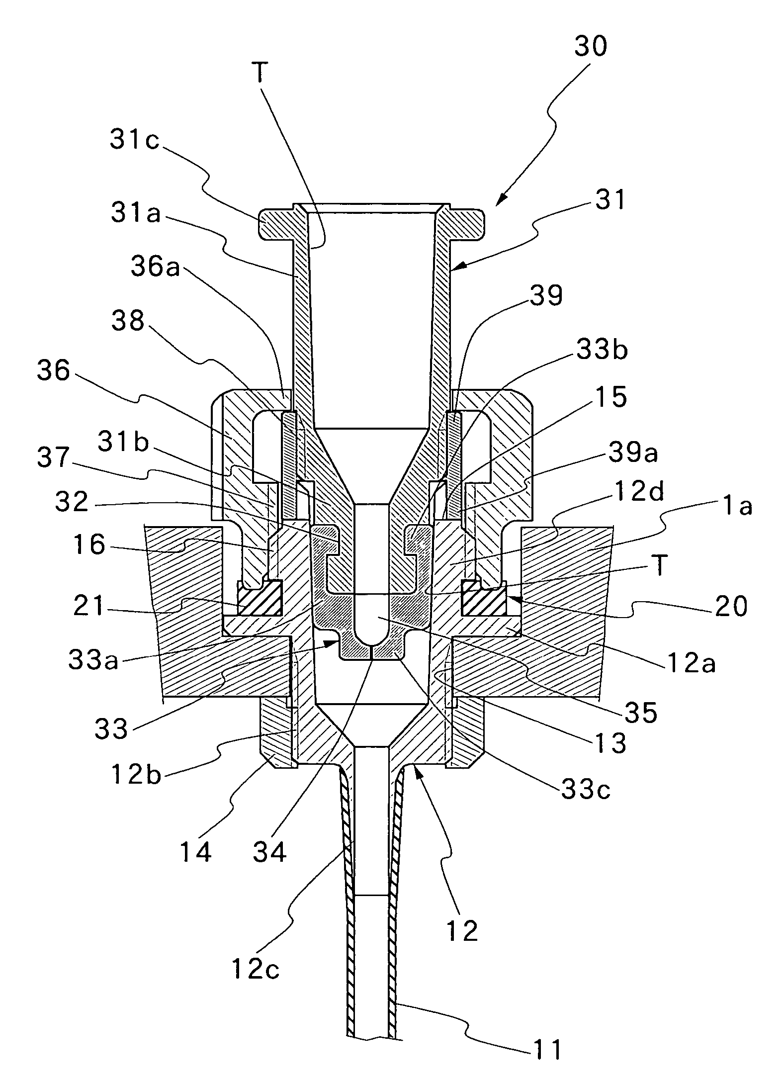
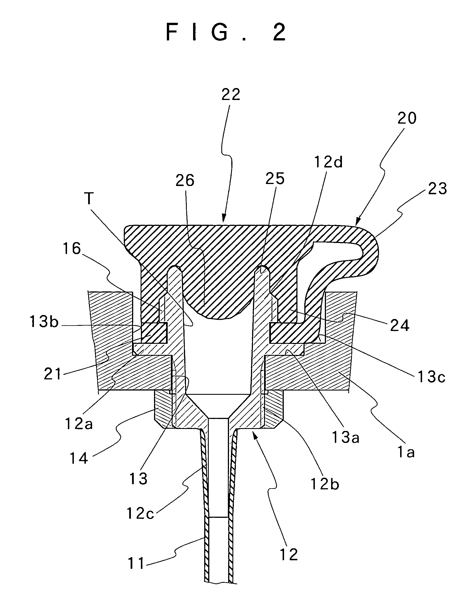
[0027]The endoscope is equipped with a liquid feed device which is also referred to as a jet injector or an auxiliary water feeder. Such water feed device includes a liquid feed port 10 whi...


PUM


Abstract

An endoscopic liquid feed device to be fitted on a mouth piece of a liquid feed port which is provided on a casing of a manipulating head assembly of an endoscope in communication with an internal liquid feed passage leading to a liquid injection port at a distal end of an insertion tube of the endoscope for injecting a liquid into a body cavity. A liquid feed adaptor is detachably fitted on the mouth piece of the liquid feed port. The liquid feed adaptor is largely constituted by a Luer-Lok member having a check valve member fitted on a fore end portion thereof, a stopper ring fitted on the outer periphery of the Luer-Lok member, and a nut member rotatably fitted on the Luer-Lok member for axial displacements between the stopper ring and a flange portion provided at the outer proximal end of the Luer-Lok member. The nut member is threaded on an external screw provided on the outer periphery of the mouth piece. A Luer-Lok portion is provided within the mouth piece, and, in place of the liquid feed adaptor, a wash liquid syringe can be connected to the Luer-Lok portion of the mouth piece at the time of washing the internal liquid feed passage of the endoscope.

Description

BACKGROUND OF THE INVENTION[0001]1. Field of the Art[0002]This invention relates to a liquid feed device for use on endoscopes, and more particularly to a liquid feed device which is especially suitable for use on endoscopes as an auxiliary water feed mechanism for spurting a jet of water or other liquids from a liquid injection port opened at a distal end of an endoscopic insertion tube.[0003]2. Prior Art[0004]Generally, a plural number of water feed / discharge means are provided on endoscopes. A first example is a body fluid suction or aspiration means. As a body fluid suction means, normally a suction passage is connected to a biopsy channel within an insertion tube of an endoscope, and a vacuum pump or a suction device is connected to the proximal end of the suction passage. At the time of aspiration, a suction valve which is provided on a manipulating head assembly of the endoscope is operated by an operator.[0005]Further, generally a wash fluid or cleaning fluid feed means is p...

Claims


Application Information

Patent Timeline
Patent Type & Authority Patents(United States)
IPC IPC(8): A61B1/12A61B1/00A61B1/012
CPCA61B1/012A61B1/00128A61B1/12
Inventor AKIBA, HARUO
Owner FUJI PHOTO OPTICAL CO LTD
Why Eureka
Try Eureka