Heating cooker

A cooker and cooking container technology, which is applied in the direction of induction heating, induction heating devices, and building material processing, can solve the problems of inability to heat cooking, high coil voltage, and high-frequency current flow, so as to avoid configuration interference, good precision effect

Inactive Publication Date: 2006-07-26
KK TOSHIBA +2
View PDF1 Cites 16 Cited by
  • Summary
  • Abstract
  • Description
  • Claims
  • Application Information

AI Technical Summary

Problems solved by technology

[0005] In the technology disclosed in Patent Document 1, there is a problem that when it is difficult to suppress the repulsive force due to the light weight of the pan, the supply of electric current is greatly restricted, and as a result, the heating power is low, and sufficient heating and cooking cannot be performed.
In addition, as in Patent Document 2, since the current flowing through the induction heating coil becomes larger when the aluminum plate is heated, the number of ultra-thin wires constituting the Litz wire must be increased, and the configuration must still be expensive.
[0007] In addition, because aluminum is a non-magnetic body with low magnetic permeability, the leakage flux of the induction heating coil is large, the number of turns of the coil is large, and the voltage of the coil is high.
Therefore, the electrostatic capacitance between the pot and the induction heating coil has the danger of applying a high voltage to the human body through the pot and flowing a high-frequency current.
In order to prevent such accidents, it is necessary to insert a shield plate between the induction heating coil and the top plate and ground it, which further complicates the structure.

Method used


Image

  • Heating cooker
  • Heating cooker
  • Heating cooker

Examples


no. 1 Embodiment

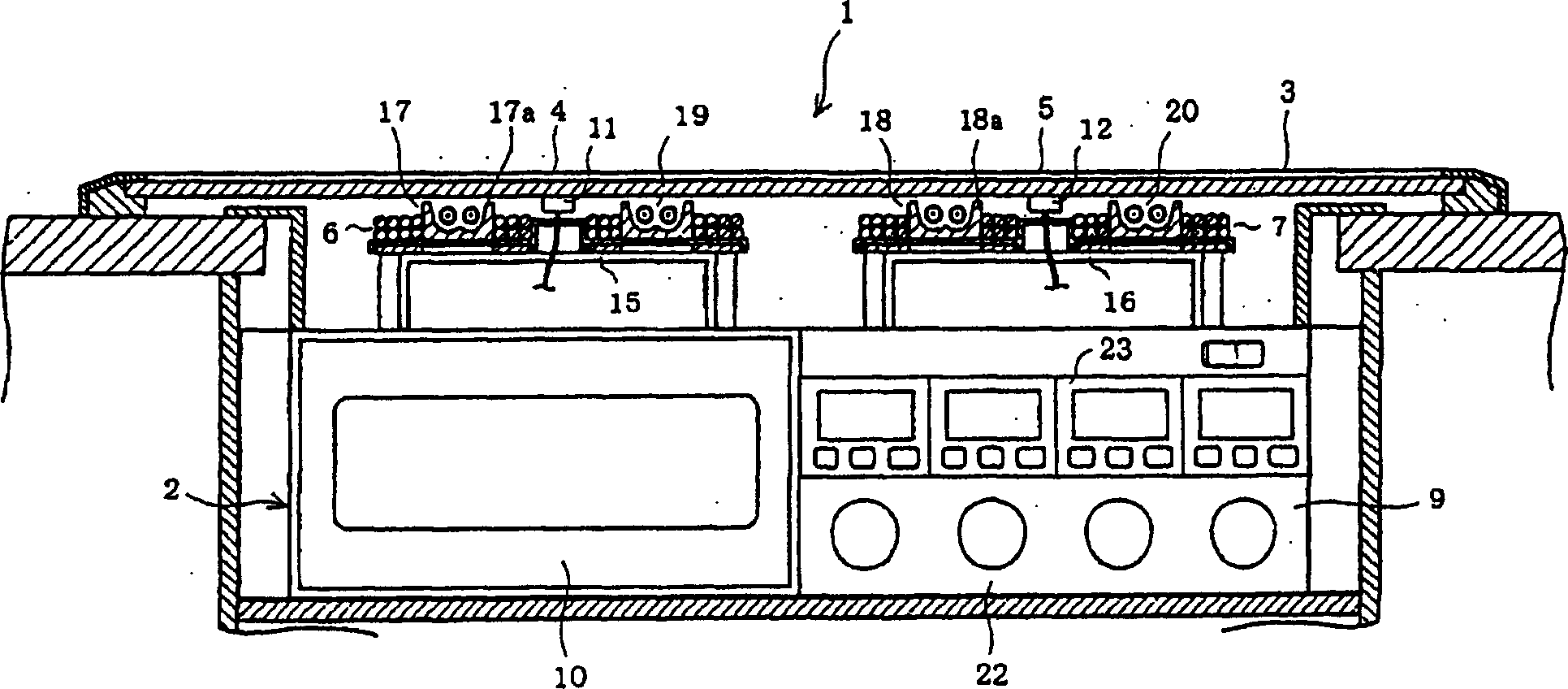
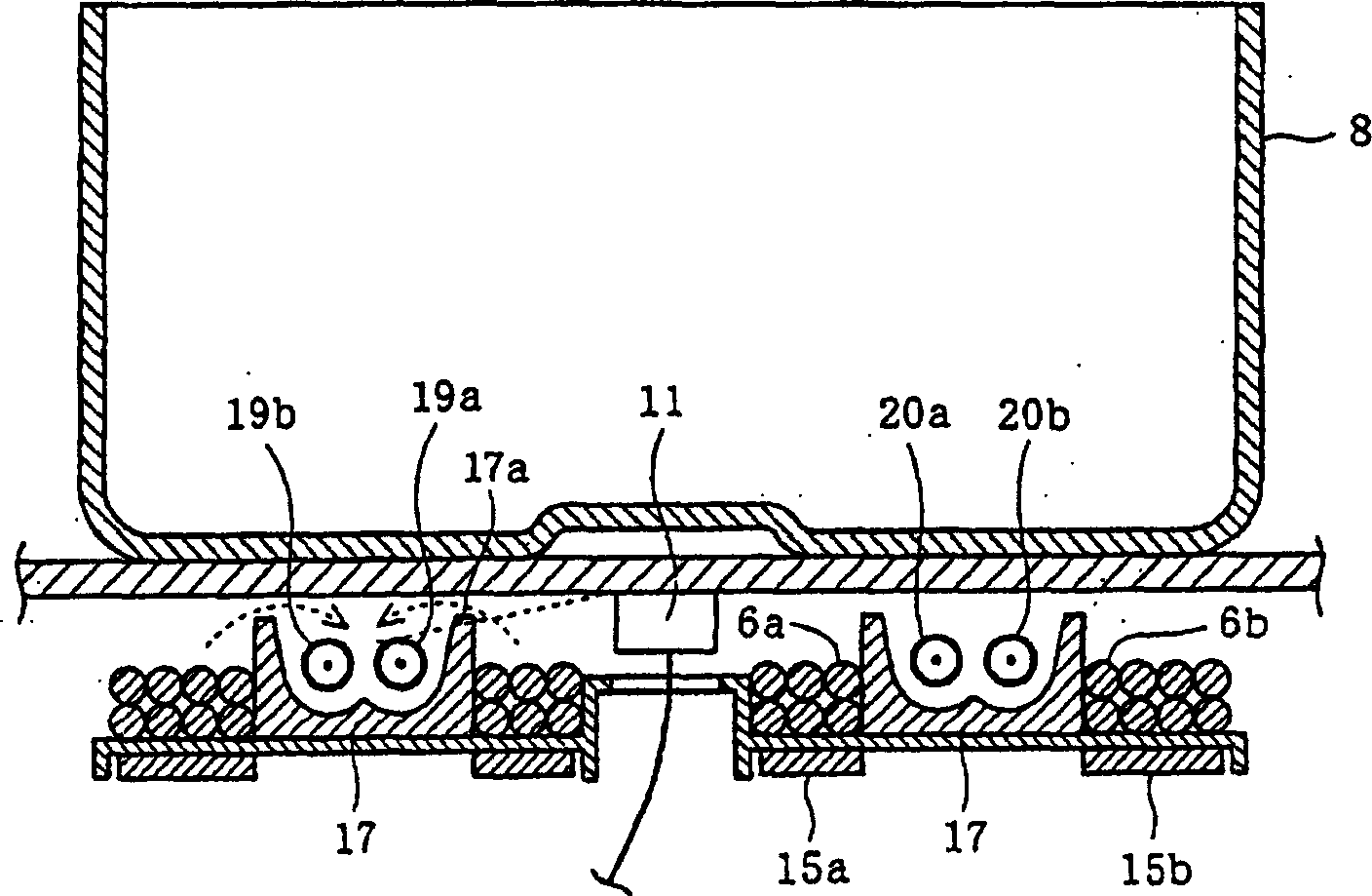
[0035] Refer to the following Figure 1 to Figure 6 The first embodiment of the present invention will be described. figure 1 A partial front view of the heating cooker 1 is shown as a longitudinal section. In the heating cooker 1, the outer casing is a casing 2, and the top plate 3 is positioned above it, and constitutes the upper surface of the casing. Inside the casing 2, induction heating coils 6, 7 are disposed directly under the mounting portions 4, 5 of the top plate 3, so that the cooking containers 8 mounted on the mounting portions 4, 5 are respectively induction heated. (refer to figure 2 ). in addition, figure 2 zoom in figure 1 part of the placement part 4.

[0036] The front of the casing 2 is provided with an operation panel 9 and a door 10 of the oven, through the operation panel 9, the user can operate the above-mentioned induction heating coils 6, 7. The inside of 2 is connected to a stove (not shown). In addition, on the lower surface of the top pl...

no. 2 Embodiment

[0065] Figure 7 The second embodiment of the present invention is shown, and the same parts as those of the first embodiment are denoted by the same reference numerals, and description thereof will be omitted, and only the different parts will be described below. The second embodiment differs in the arrangement of the induction heating coils and the infrared heaters on the lower side of the top plate 3 . That is, its composition as equivalent to figure 2 of Figure 7 As shown, the induction heating coil 31 wound in two stages is arranged on the central side of the mounting part 4, and the infrared heater support 32 and two infrared ring heaters 33a, 33b are arranged on the outer peripheral side. The induction heating coil 31 and the infrared ring heaters 33A, 33b constitute a heating unit 61 .

[0066] The same effect as that of the first embodiment can be obtained also in the second embodiment having the above-mentioned structure.

no. 3 Embodiment

[0068] Figure 8 A third embodiment of the present invention is shown. The third embodiment also shows an example in which the configurations of the induction heating coils and the infrared heaters on the lower side of the top plate 3 are different, as in the second embodiment. That is, if Figure 8 shown. The infrared heater support 34 is arranged on the central side of the mounting portion 4 , and the infrared band-shaped heater 35 is arranged in a state of being wound in multiple turns inside the infrared heater support 34 . An induction heating coil 36 wound in two stages is disposed on the outer peripheral side of the infrared band heater 35 .

[0069] In addition, the side wall forming the infrared heater support body 34 is the same as the infrared heater support bodies 17, 32 in the first and second embodiments, so that the infrared rays having the function of preventing the radiation of the infrared band-shaped heater 35 are irradiated to the temperature detection. F...


PUM


Abstract

The present invention provides a heating cooker capable of further efficiently heating cookware to be heated that is made of a low-permeability material. This heating cooker comprises an induction heating coil 6 and an infrared heater 19 for heater heating. A heating power controller determines the material of the cookware 8 to be heated and controls an inverter and a heating element conducting section according to the material determined, thereby controlling the heating ratio between the induction heating coil 6 and the infrared heater 19. A temperature detection part 11 is disposed inside the infrared heater 19 forming a ring-like shape; and a heater installation member 17 is so structured that its side wall 17a prevents an infrared ray radiated from the infrared heater 19 from reaching the temperature detection part 11.

Description

technical field [0001] The present invention relates to a heating cooker including a heating unit including an induction heating coil and an infrared heater for heating a cooking container placed on a top plate constituting an upper surface of a casing. technical background [0002] In an induction heating cooker, how to heat a cooking vessel made of a material with low magnetic permeability and high conductivity such as an aluminum pot or a copper pot has become a problem. As a conventional technique for solving this problem, Patent Document 1 discloses a configuration that detects the floating or movement of the pan due to the repulsive force generated during induction heating, and limits the current supplied to the induction heating coil. In addition, Patent Document 2 discloses a configuration in which an aluminum plate is inserted between an induction heating coil and a pan, and the pan is indirectly heated by induction heating the aluminum plate. [0003] [Patent Docu...

Claims


Application Information

Patent Timeline
Patent Type & Authority Applications(China)
IPC IPC(8): H05B6/12H05B11/00
CPCE04G21/246
Inventor 松尾胜春江碕猛
Owner KK TOSHIBA
Why Eureka
Try Eureka