Knee prosthesis with a flexion hinge

Active Publication Date: 2006-01-10
WALDEMAR LINK GMBH & CO
View PDF19 Cites 119 Cited by
  • Summary
  • Abstract
  • Description
  • Claims
  • Application Information

AI Technical Summary

Benefits of technology

[0004]To simplify the assembly, the pin stumps can be subject to the spreading force of a spring which moves them apart into the mounted position as soon as they are able to do so on reaching the receiving bores in the fork branches. For example, at the start of assembly, the centre part of the hinge is held between thumb and index finger in such a way that the pin stumps are pressed into the centre part. The latter is then pushed into the space between the

Problems solved by technology

This makes necessary a corresponding insertion opening in one of the femoral condyles, which adversely weakens the bone and involves a

Method used


Image

  • Knee prosthesis with a flexion hinge
  • Knee prosthesis with a flexion hinge
  • Knee prosthesis with a flexion hinge

Examples


Embodiment Construction

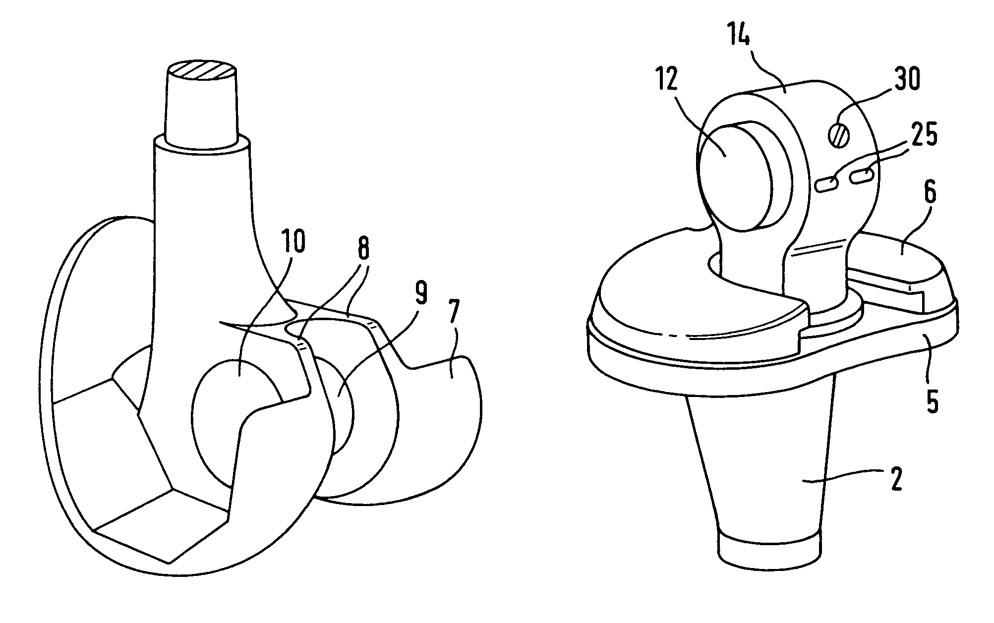
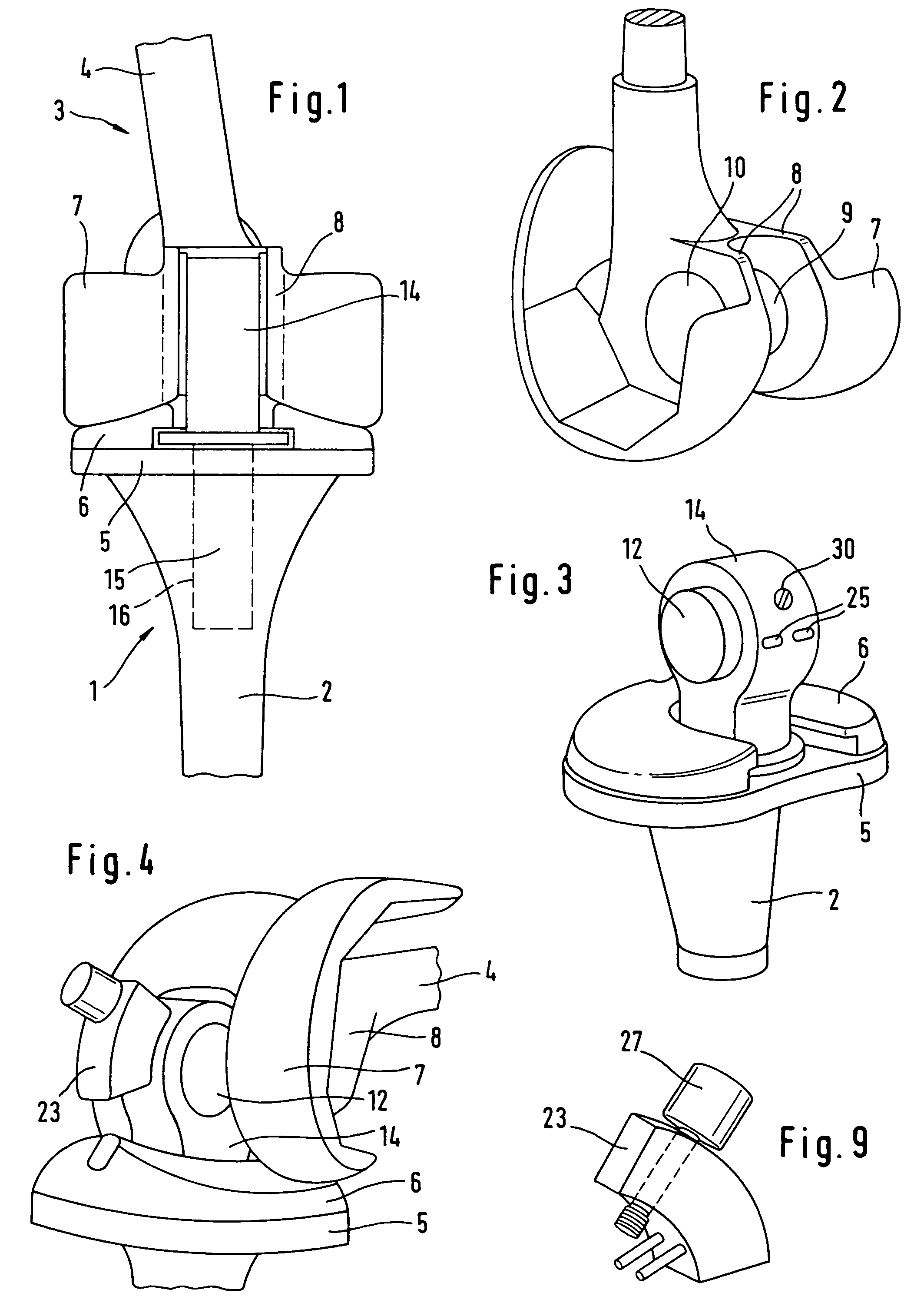
[0019]The prosthesis consists of a tibial component 1 whose stem 2 is to be implanted in the tibia, and of a femoral component 3 whose stem 4 is to be implanted in the femur. At the top, the tibial component 1 ends in a plate 5 which carries a polyethylene plateau 6 whose top forms a slide surface for the runners 7 of the femoral component. The vertical load is transmitted via these parts.

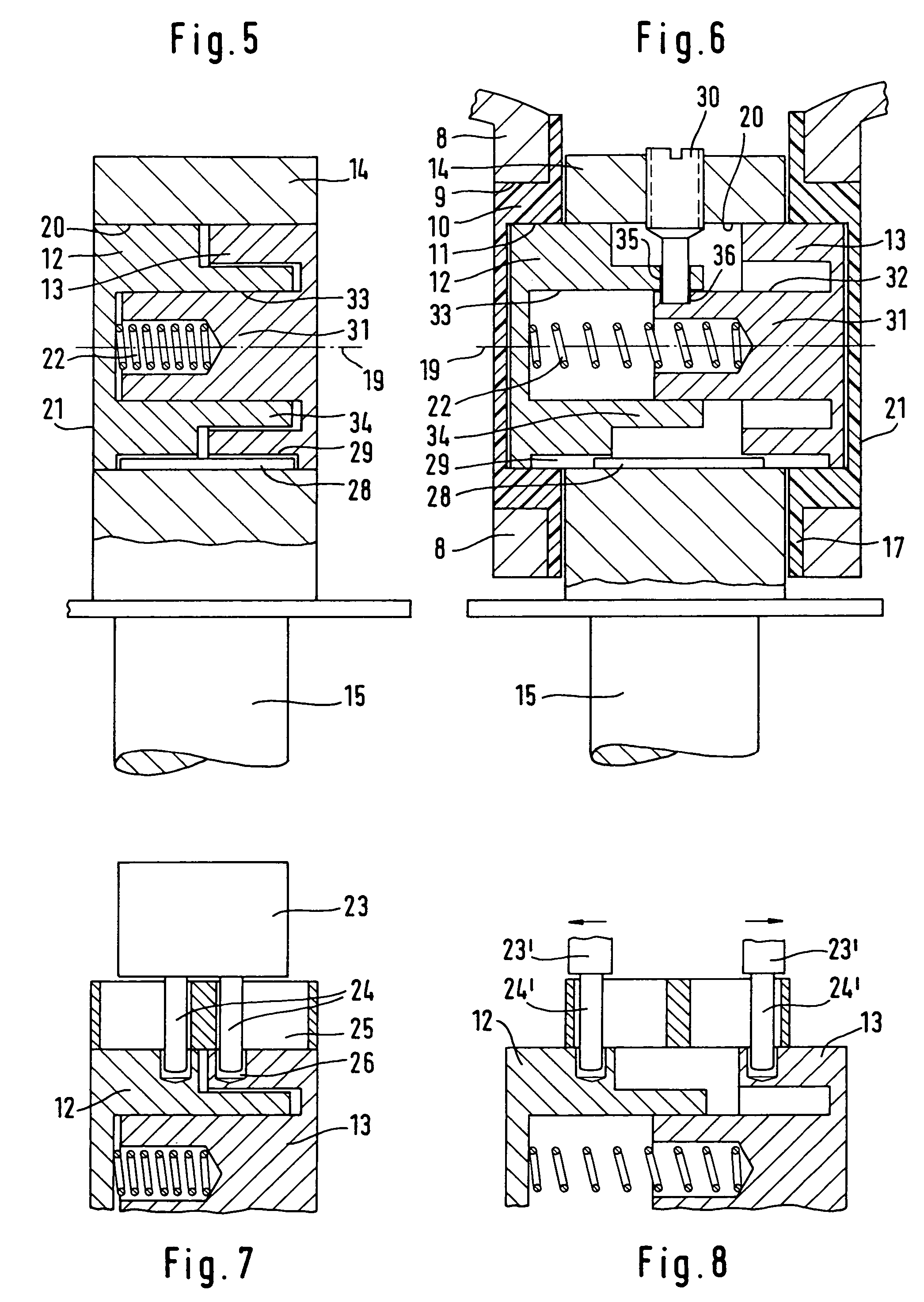
[0020]To stabilize the components 1 and 3, a stabilizing arrangement is provided forming a hinge, which permits a flexion movement between the components 1 and 3, and a rotation bearing. The femoral component 3, with the plates 8 arranged parallel to one another in a box shape, forms a hinge fork with receiving bores 9 which are lined by hat-shaped polyethylene bearing parts 10 which form a hollow cylindrical bearing face 11. Mounted therein are pin parts 12, 13 whose other ends are arranged in the hinge centre part 14 which is arranged integrally on the upper end of a journal 15 which is mounted s...


PUM


Abstract

A knee prosthesis with a flexion hinge which is formed by a hinge fork with two branches lying opposite each other, by a center part which is to be fitted in the hinge fork transversely with respect to the flexion axis of the latter, and by a hinge pin which, after the center part has been fitted into the hinge fork, is to be mounted, by movement in its longitudinal direction, in aligned hinge bores of the hinge fork and of the center part. So as not to have to push the pin into the prosthesis from the outside, it is formed by two pin stumps which, in an assembly position, are arranged inside the center part and, in a mounted position, partially protrude from the latter.

Description

FIELD AND BACKGROUND OF THE INVENTION[0001]The invention relates to knee prostheses which have a hinge for determining the flexion movement. This can be a hinge which is used exclusively for stabilization (DE-C-31 19 841, EP-A-716 839, EP-A-791 343, EP-A-420 460) or which transmits the full load (GB-C-1 305 391, EP-A-278184, FR-C-2 161 588, U.S. Pat. No. 3,772,709). The hinge is in each case formed by a hinge fork which is normally connected to the femur, and by a hinge centre piece which is connected to the tibia. The branches of the hinge fork and the centre piece have aligned bores through which a hinge pin passes. Generally, the femoral and tibial components of the prosthesis are first implanted separately and then connected to one another. In those cases where only the hinge pin connects the components to one another, it is pushed into the associated receiving bores from the side after the components have been implanted. This makes necessary a corresponding insertion opening in...

Claims


Application Information

Patent Timeline
IPC IPC(8): A61F2/38A61F2/30
CPCA61F2/385A61F2/3859A61F2002/30878A61F2002/30566A61F2002/30632A61F2/389A61F2/38
Inventor KELLER, ARNOLD
Owner WALDEMAR LINK GMBH & CO
Why Eureka
Try Eureka