Arrangement and method for installing a subsea transformer

a transformer and installation method technology, applied in the field of offshore installations, can solve the problems of less control of the components, significant risk of damage to the components, and complicated installation process of these components, and achieve the effect of simplifying the installation process and facilitating the entry of the guide pin

Inactive Publication Date: 2006-01-10
VETCO GRAY SCANDINAVIA
View PDF11 Cites 65 Cited by
  • Summary
  • Abstract
  • Description
  • Claims
  • Application Information

AI Technical Summary

Benefits of technology

[0009]The object of the present invention is to provide a device and a method, which eliminates the drawbacks described above.
[0010]More specifically, the main object of the present invention is to develop a device that may be integrated with subsea components to secure and simplify the installation process.
[0011]In short, in a preferred embodiment of the invention, the object is achieved by introducing a central, (through-going or not) tube (from now on referred to as a receiving channel) in the encapsulation enclosing the transformer which is to be installed. The core elements of the transformer are arranged symmetrically around the receiving device forming a triangle or a delta. In the installation process, a single guide pin mounted in the foundation placed on the sea floor will enter the receiving channel, and the encapsulation will slide down on the guide pin. The receiving channel is terminated by a funnel shaped opening, thus making it easier to enter the guide pin.

Problems solved by technology

The installation process of these components may be both complicated and demanding because of the strong and unpredictable environment the installers encounter.
Additionally, the installers have less control over the components because the installation often has to be done remotely, e.g. from a boat.
Thus, during the process, there is a considerable risk of damaging the components, and if the installation fails, there are often limited possibilities for correction.
Installation of transformers used in subsea power distribution systems is an example of such a risky installation process.
The main drawback of the installation process mentioned above is that large objects, in particular rectangular ones, are widely exposed to underwater currents when being lowered.
Experience has shown that they tend to twist around during deployment, especially in depths where guide wires are not used.
This fact makes it difficult to enter the guide pins with the funnels placed at the edges of the transformers, all at the same time.
A further drawback is that the transformer risks to jam / wedge between the guide pins, if the installation fails.
This may cause damage, or even loss, of the transformer which is to be installed.
Moreover, the transformer may be overturned by the guide pins when sighting the transformer, and this may also cause damage or loss.

Method used


Image

  • Arrangement and method for installing a subsea transformer
  • Arrangement and method for installing a subsea transformer
  • Arrangement and method for installing a subsea transformer

Examples


Embodiment Construction

[0018]With reference to the abovementioned figures, there will in the following be described three exemplary embodiments of the present invention.

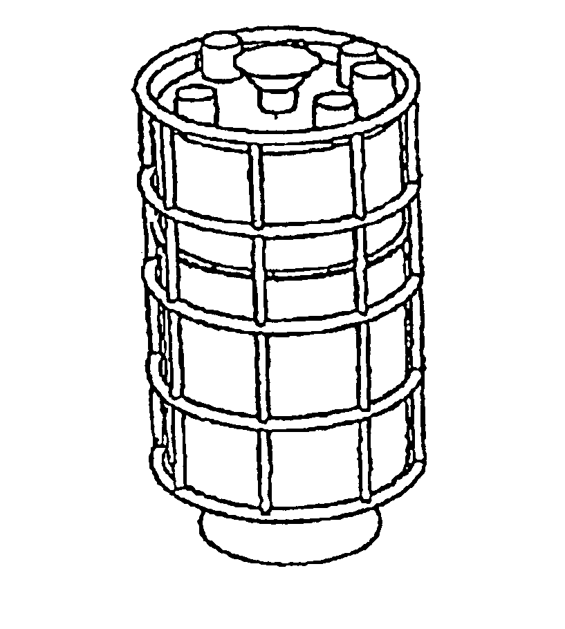
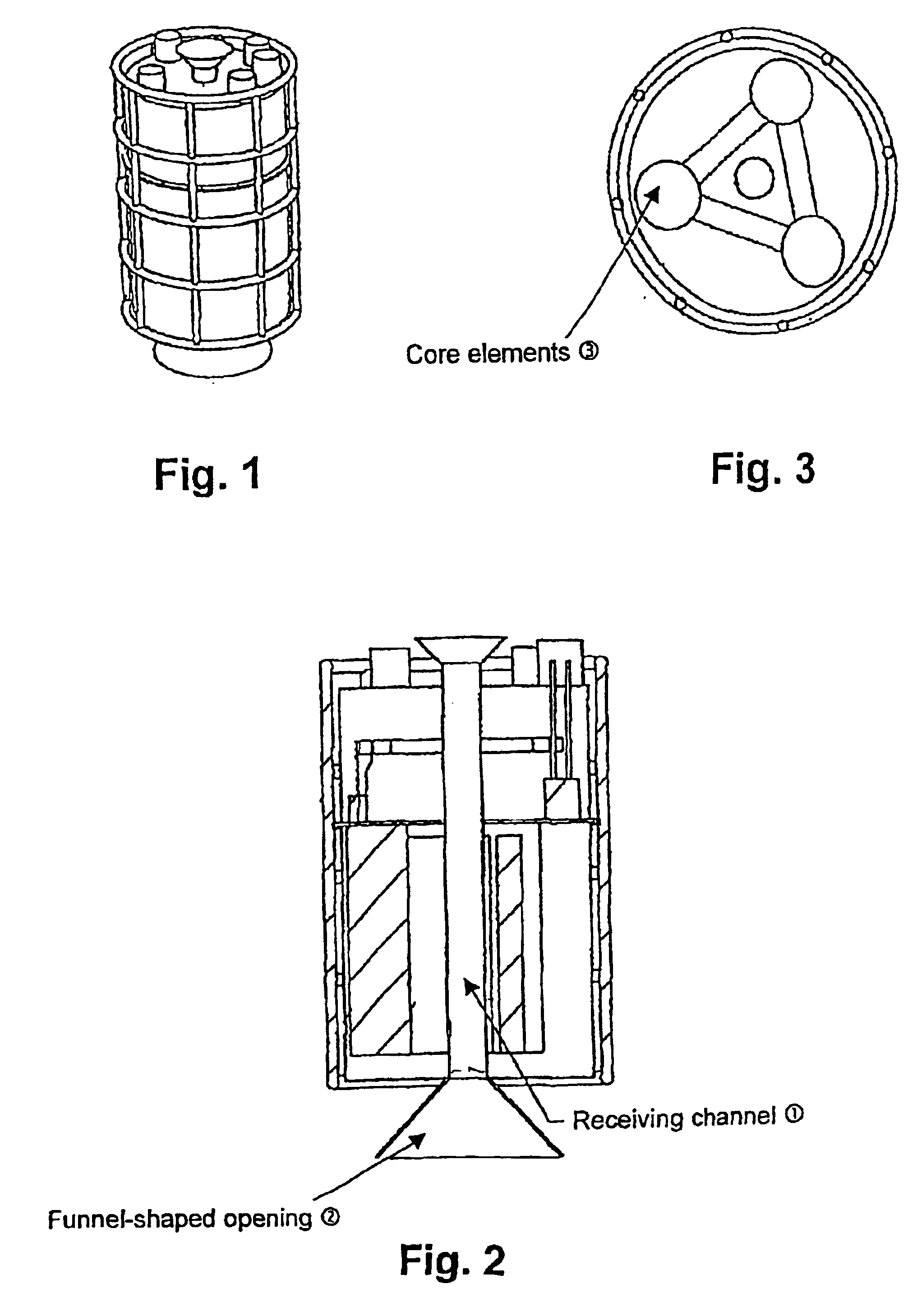
[0019]FIG. 1 shows a cylindrical subsea transformer including the receiving channel of the present invention. In this embodiment, the receiving channel (1) runs through the transformer from the top, all the way to the bottom. The channel does not necessarily have to be through-going. However, it has to be localized in the centre of the cylinder forming the transformer body.

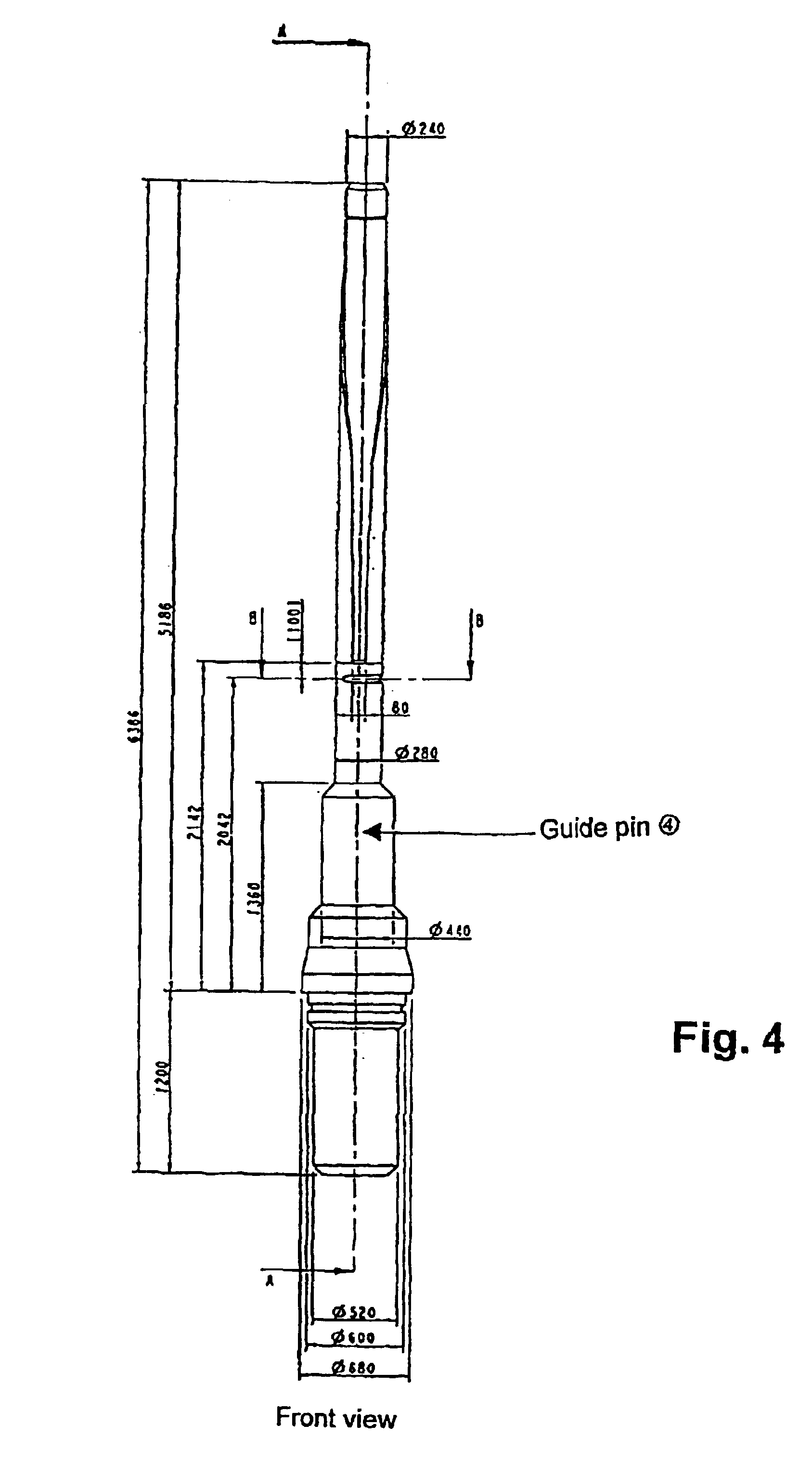
[0020]This is illustrated even better in FIG. 2, which shows a sectional elevation of the transformer. The receiving channel (1) is placed at the exact center to make it possible to use only one guide pin (4) in the installation process. Moreover, the centering makes the transformer more stable and easier to handle during installation.

[0021]It is also shown that the receiving channel (1) is terminated at the bottom by a funnel-shaped opening (2). This is done for “broade...


PUM

PropertyMeasurementUnit
depthsaaaaaaaaaa
timeaaaaaaaaaa
distanceaaaaaaaaaa

Abstract

An arrangement and a method for use in installation procedures for subsea transformers. A central, hole or tube is included in an encapsulation enclosing a transformer that is to be installed. Three core elements of the transformer are arranged symmetrically around the hole or tube forming a triangle or a delta. The transformer is lowered towards a a foundation placed on the sea floor wherein a guide pin is mounted. When the transformer has found its way to the foundation, the guide pin will enter the tube, and the transformer will slide down onto the guide line pin. The tube is terminated by a funnel shaped opening, thus making it easier not to miss the guide pin by the tube opening. The transformer is horizontally oriented by means of orientation keys localized within the tube.

Description

FIELD OF THE INVENTION[0001]The present invention relates to offshore installations, and in particular to an arrangement and a method for use in installation procedures for subsea transformers.BACKGROUND OF THE INVENTION[0002]Today's offshore industry requires a great deal of subsea completions. Especially, the subsea power distribution systems to and between e.g. oil platforms or other offshore power consumers, include a lot of relatively large and heavy components, such as transformers.[0003]The installation process of these components may be both complicated and demanding because of the strong and unpredictable environment the installers encounter. Additionally, the installers have less control over the components because the installation often has to be done remotely, e.g. from a boat. Thus, during the process, there is a considerable risk of damaging the components, and if the installation fails, there are often limited possibilities for correction.[0004]Installation of transfo...

Claims


Application Information

Patent Timeline
Patent Type & Authority Patents(United States)
IPC IPC(8): H01F27/02E21B33/035E21B41/00H01F27/06
CPCE21B33/0355H01F27/06H01F27/02E21B41/0014
Inventor HAFSKJOLD, GUNNARSOELVIK, NILS ARNE
Owner VETCO GRAY SCANDINAVIA
Why Eureka
Try Eureka