Dual-polarization antenna array

Inactive Publication Date: 2006-01-10
TELEFON AB LM ERICSSON (PUBL)
View PDF43 Cites 95 Cited by
  • Summary
  • Abstract
  • Description
  • Claims
  • Application Information

AI Technical Summary

Benefits of technology

[0008]Against the background of this prior art, the technology herein improves a dual-polarized single-band, dual-band and/or multiband antenna array such that, with a depression angle which can be set differently, it is possible to compensate better for, or even to prevent, the polarization-dependent polar diagrams drifting apart from one another.
[0009]It is surprising that, according to an exemp

Problems solved by technology

Although the possibility of depressing the antenna to different extents by varying the phase angles of the individual antenna elements is intrinsically very highly advantageous for adaptation of the illumination in situ, it has been found to be disadvantageous in the case of antennas having a polarization of +/−45°.
In this case, it has been found to be particularly disadvantageous that, when the vertical polar diagram depression is

Method used


Image

  • Dual-polarization antenna array
  • Dual-polarization antenna array
  • Dual-polarization antenna array

Examples


Example

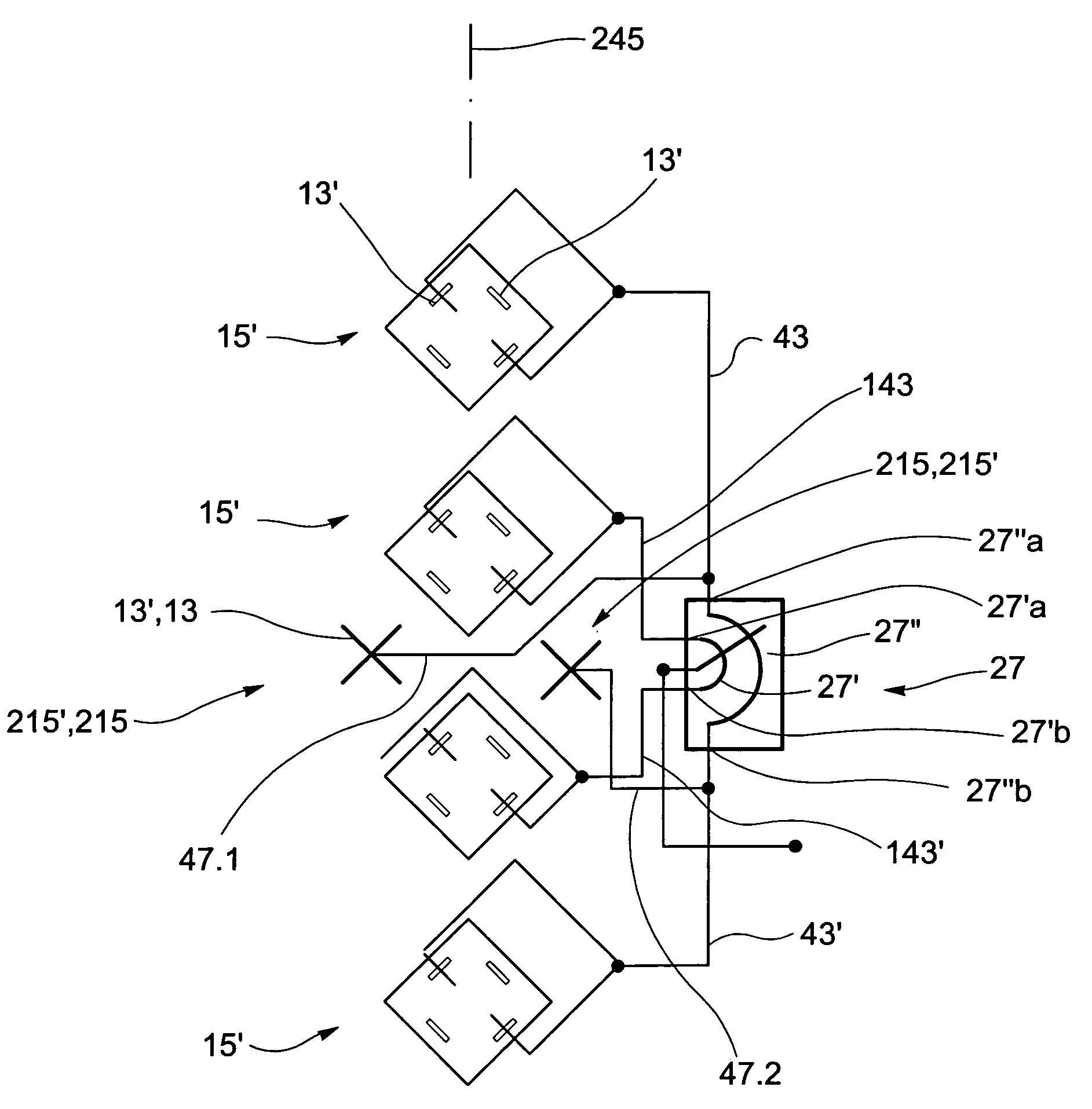
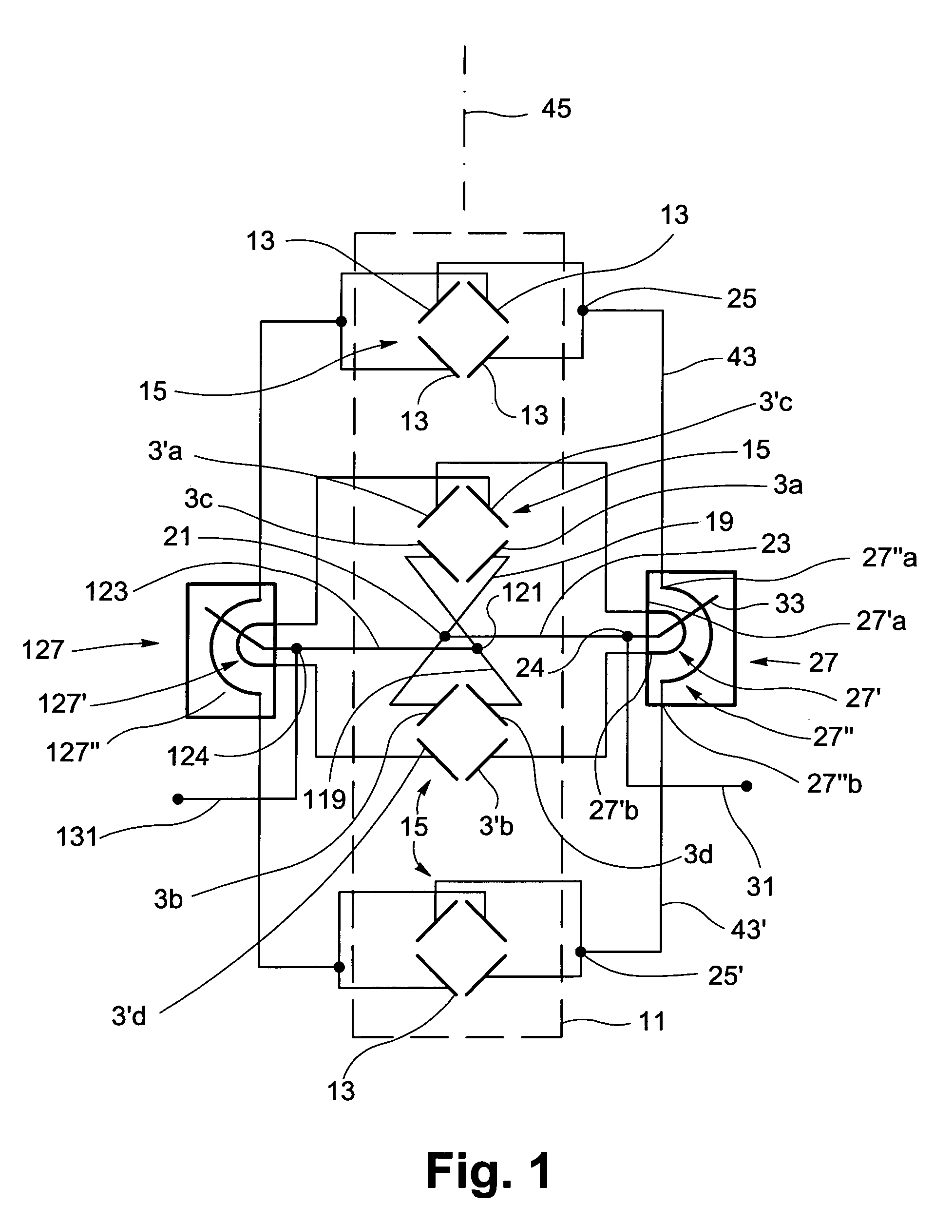
[0029]FIG. 1 shows an exemplary illustrative non-limiting dual-polarized antenna array. This comprises a large number of individual antenna elements 13 in front of a vertically aligned reflector 11, with four individual antenna elements 13 in each case forming a dipole square 15 in the illustrated exemplary arrangement. According to the exemplary non-limiting arrangement shown in FIG. 1, four dipole squares 15 are arranged one above the other, fitted in the vertical direction, in front of the reflector 11. The individual antenna elements 13 in this case comprise dipole antenna elements, which are each arranged at an angle of +45° or −45° with respect to the vertical or horizontal, so that it is also possible to refer to this as a short X-polarized antenna array.

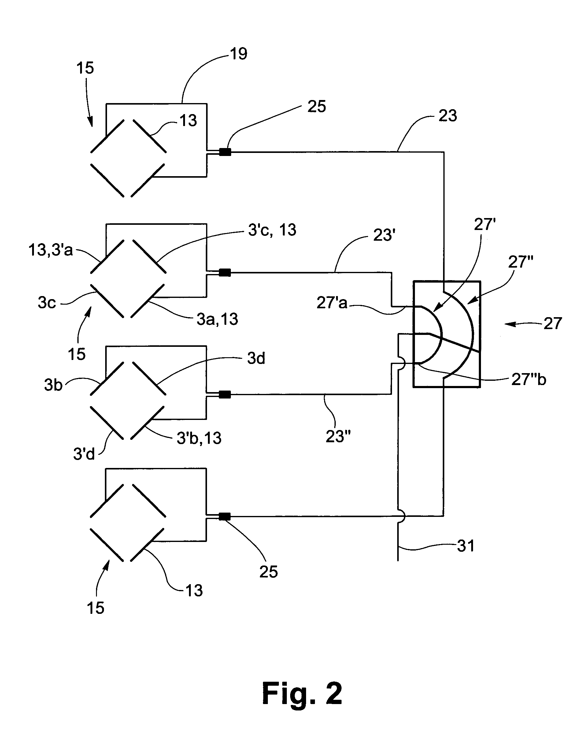
[0030]FIG. 1 shows that, by way of example, the individual antenna element 3a, which is aligned at an angle of +45° to the horizontal, of the second dipole square 15, counting from the top, is connected via a line 19 and via ...


PUM


Abstract

An improved antenna array, having at least two groups of individual antenna elements comprising a dipole square and/or patch antenna elements with a square antenna element structure. Individual antenna element arranged at least horizontally offset with respect to one another are provided for each of the two polarizations which are at right angles to one another. At least two additional antenna elements are horizontally offset with respect to one another, and/or at least two pairs of vertically aligned individual antenna elements, which are arranged with a horizontal offset with respect to one another, are provided for each of the two orthogonal polarizations. The individual antenna elements which are in each case arranged with a horizontal offset with respect to one another and are aligned parallel to one another are fed with different phase angles as a function of the depression angle.

Description

CROSS-REFERENCES TO RELATED APPLICATIONS[0001]This application is the US national phase of international application PCT / EP02 / 10885 filed 27 Sep. 2002, which designated the US.STATEMENT REGARDING FEDERALLY SPONSORED RESEARCH OR DEVELOPMENT[0002]Not applicable.FIELD[0003]The technology herein relates to a dual-polarized antenna array.BACKGROUND AND SUMMARY[0004]Dual-polarized antennas are preferably used in the mobile radio field for 800 MHz to 1000 MHz, and in the band from 1700 MHz to 2200 MHz. The antennas transmit and receive two orthogonal polarizations. In particular, the use of two linear polarizations aligned at +45° and −45° with respect to the vertical or horizontal have been proven in practice. Dual-polarized antennas aligned in this way are also frequently referred to as X-polarized antennas. In order to optimize the illumination of the supply area, without needing to mechanically depress the antenna, the polar diagram is depressed electrically by changing the phase angle...

Claims


Application Information

Patent Timeline
IPC IPC(8): H01Q9/28H01Q21/00H01Q9/16H01Q13/08H01Q21/24
CPCH01Q21/24H01Q3/32
Inventor GOTTL, MAXIMILIAN
Owner TELEFON AB LM ERICSSON (PUBL)
Why Eureka
Try Eureka