Dot matrix display device

Inactive Publication Date: 2006-01-10
TEXAS INSTR INC
View PDF3 Cites 39 Cited by
  • Summary
  • Abstract
  • Description
  • Claims
  • Application Information

AI Technical Summary

Benefits of technology

[0012]In another aspect of the dot matrix display device of this invention, preferably, in addition to the above-mentioned basic construction, it can be further equipped with switches that are connected in series with the above-mentioned rectifying elements between the above-mentioned scanning electrodes and the above-mentioned reference voltage terminal, and a switch control means that places the above-mentioned switches in the ON state only for a prescribed time during a period in which the drive voltage is supplied to the above-mentioned scanning electrodes.
[0013]Also, in addition to the above-mentioned basic construction, it can be provided with a scanning electrode drive means that sequentially dr

Problems solved by technology

But, in this type of display used in the past, there are instances LEDj1, LEDj2, LEDj3 on other common lines CLj that have not been selected are caused to emit undesired erroneous light

Method used


Image

  • Dot matrix display device
  • Dot matrix display device
  • Dot matrix display device

Examples


Embodiment Construction

[0036]Below, embodiments of this invention are explained based on FIGS. 1-6.

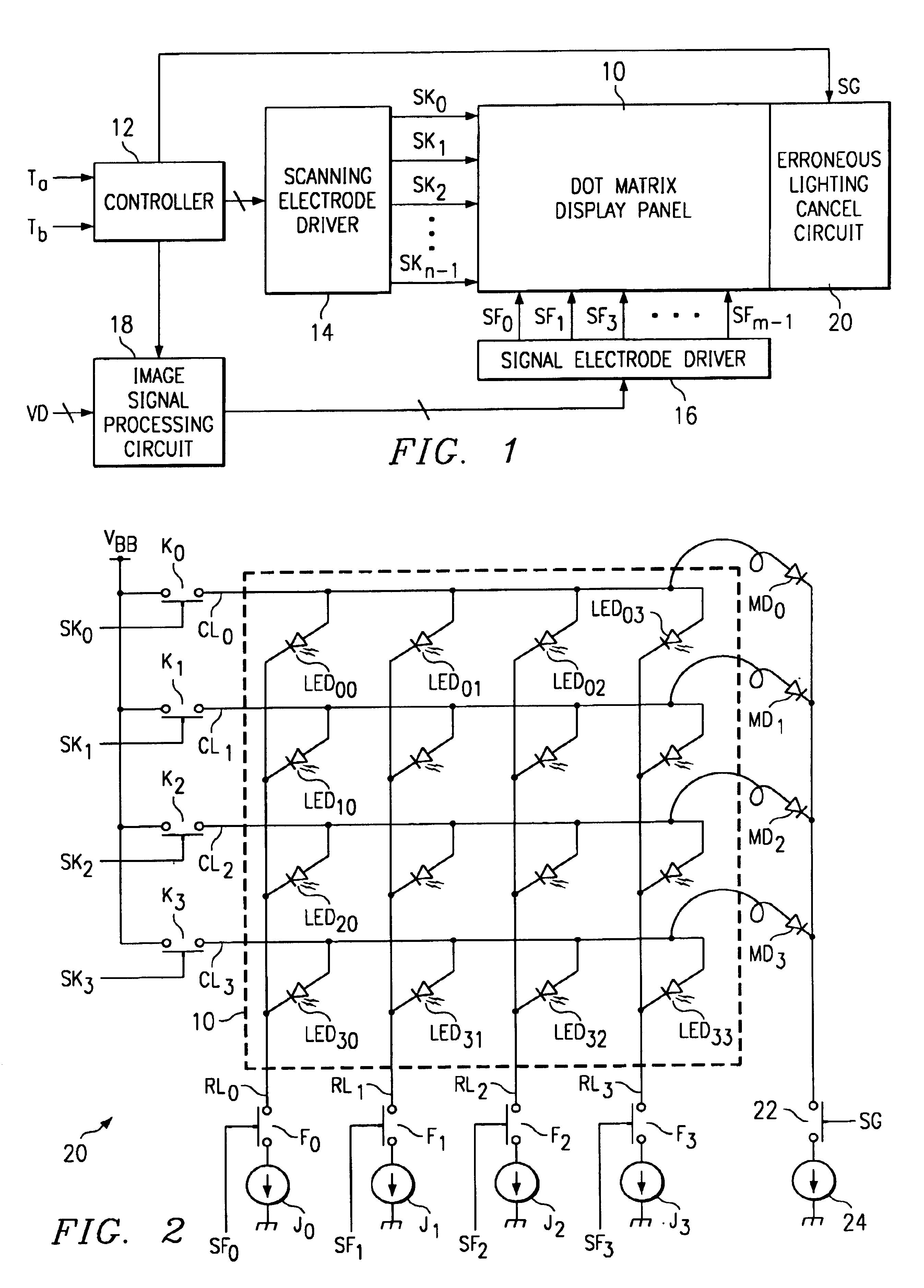
[0037]In FIGS. 1 and 2, the construction of a dot matrix display with a dynamic drive system according to one embodiment of this invention is shown. In FIG. 3, the timing for the essential signals in this display is shown.

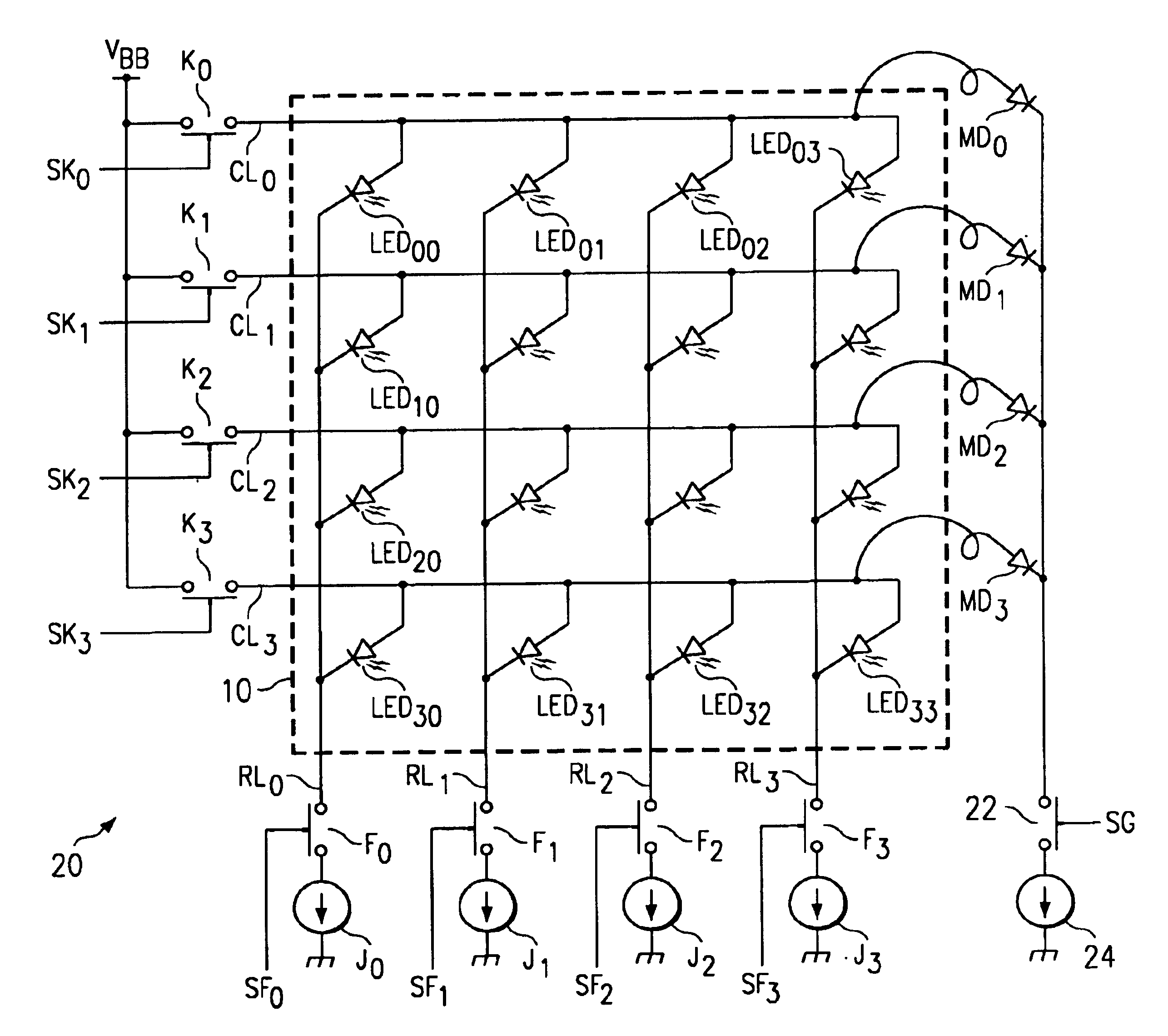
[0038]As in FIG. 2, the dot matrix display panel 10 can use the same device as in the past. In other words, in this display panel 10, along with the common lines CL0, CL1, CL2, CL3 arranged at a constant pitch in the vertical direction and expanding in the horizontal direction as the scanning electrodes, the signal lines RL0, RL1, RL2, RL3 are arranged at a constant pitch in the horizontal direction and expanding in the vertical direction as the signal electrodes, and LEDs (light emitting diodes) used as display elements at each intersection point of the matrix are arranged with the anodes connected to a common line CL and the cathodes connected to a signal line RL, respectively. The common...


PUM


Abstract

To improve the display quality in the scanning of a dynamic drive system by effectively preventing the erroneous display of the display elements that are connected to the scanning electrodes during non-selection. The erroneous lighting cancel circuit 20 has a number of (or assemblies of) dummy diodes MD used for erroneous lighting prevention that is equal to the number of common lines CL, and along with the anode of each dummy diode MD0, MD1, MD2, MD3 being electrically connected to each corresponding common line CLO, CL1, CL2, CL3 by means of suitable wiring, the cathode of each dummy diode MD0, MD1, MD2, MD3 is electrically connected to a terminal of a reference potential (for example, ground potential) through the medium of a shared switch 22 and a constant current source circuit (active load) 24. The control signal SG reaches an active state (H level) only for a prescribed time during the scanning drive period for each horizontal scanning period, and the switch 22 is placed in the ON state. During this prescribed time, the positive charge that is present on each common line CLO, CL1, CL2, CL3 is discharged at a constant current to the ground side through the medium of each dummy diode MD0, MD1, MD2, MD3, the ON state of the switch 22, and the constant current source circuit 24.

Description

FIELD OF THE INVENTION[0001]This invention relates to a dot matrix display device in which the display elements for one dot portion are arrayed in a matrix form, and in particular, relates to a dot matrix display device with a dynamic drive system that conducts the display of images by driving display elements one row at a time in a selective matrix configuration with a prescribed scanning system within a period for one frame.BACKGROUND OF THE INVENTION[0002]In FIG. 7, the basic construction of a dynamic drive type dot matrix display device is shown. In this display, along with the common lines CL0, CL1, CL2, CL3 that extend in the horizontal direction as scanning electrodes arranged at a fixed pitch in the vertical direction, the signal lines RL0, RL1, RL2, RL3 that extend in the vertical direction as signal electrodes are arranged at a fixed pitch in the horizontal direction, and LEDs (light emitting diodes) are arranged with the anodes connected to the common lines CL) and the ca...

Claims


Application Information

Patent Timeline
IPC IPC(8): G09G3/20G09G3/32G09F9/33
CPCG09G3/32G09G3/3216G09G2320/0209G09G2320/02G09G2310/0248
Inventor NOGAWA, MASASHI
Owner TEXAS INSTR INC
Why Eureka
Try Eureka