
Projection type optical display system

a projection type, optical display technology, applied in the direction of projection devices, polarising elements, instruments, etc., can solve the problems of reducing the contrast ratio reducing the cost and size of the single-panel type, and reducing the cost and size of the three-panel type. , to achieve the effect of minimizing the contrast ratio

Inactive Publication Date: 2006-01-10
SHARP KK
View PDF14 Cites 16 Cited by
  • Summary
  • Abstract
  • Description
  • Claims
  • Application Information

AI Technical Summary

Benefits of technology

[0017]In order to overcome the problems described above, preferred embodiments of the present invention provide a projection type optical display system with the decrease in contrast ratio minimized.

Problems solved by technology

However, the three-panel type needs a greater number of components than a single-panel type.
Thus, the three-panel type is normally less advantageous than the single-panel type in respects of cost and size.
In such a projection type optical display system, however, incoming white light is absorbed into the color filters and only one-third of the incoming white light can be used.
As a result, leakage of light is created in the black state to decrease the contrast ratio.
Thus, the decrease in the contrast ratio of the image is significant in such a situation.
Accordingly, the balance among the outgoing R, G and B light rays will be disturbed, thereby making it difficult to reproduce color white or creating color unevenness.
Thus, the light that has been emitted from the light source cannot be used so efficiently as in the three-panel type (that uses light with a degree of parallelism of about 11 degrees).
However, when light enters the liquid crystal panel at as high a light receiving angle as 26 degrees, the leakage of light will be quite perceivable and the decrease in contrast ratio will be significant.
Also, in the liquid crystal layer described above, the greater the angle of incidence of the incoming light, the greater the quantity of light leaking therefrom.

Method used


Image

  • Projection type optical display system
  • Projection type optical display system
  • Projection type optical display system

Examples


embodiment 1

[0113]FIG. 4 is a schematic representation of a three-panel projection type optical display system according to a first specific preferred embodiment of the present invention.

[0114]As shown in FIG. 4, the three-panel projection type optical display system of the first preferred embodiment includes an illumination optical system 1000, a color separation optical system 1100, a relay optical system 1200, three liquid crystal panels 107R, 107G and 107B, three field lenses 105 provided for the respective panels 107R, 107G and 107B, a dichroic prism 109 and a projection lens 108.

[0115]The illumination optical system 1000 includes a light source 101, a reflector 102, lens arrays 103 and a condenser lens 104. The color separation optical system 1100 includes dichroic mirrors 106a and 106c and a reflective mirror 106b. The relay optical system 1200 includes reflective mirrors 106d and 106e.

[0116]The white light, which has been emitted from the light source 101 of the illumination optical sy...

embodiment 2

[0139]FIG. 15 is a schematic representation of a single-panel projection type optical display system according to a second specific preferred embodiment of the present invention.

[0140]As shown in FIG. 15, the projection type optical display system of the second preferred embodiment includes an illumination optical system 2000, a color separation optical system 2100, a liquid crystal panel a field lens 208 and a projection lens 209.

[0141]The illumination optical system 2000 includes a light source 201, a reflector 202 and a lens 203.

[0142]The color separation optical system 2100 includes three dichroic mirrors 206a, 206b and 206c, which are not arranged parallel to each other but substantially in a fan shape. By arranging the dichroic mirrors 206a, 206b and 206c in such a shape, the outgoing light rays of the illumination optical system 2000 are incident onto the dichroic mirrors 206a, 206b and 206c at mutually different angles.

[0143]The liquid crystal panel 207 has the same arrangem...

embodiment 3

[0156]FIG. 21 is a schematic representation of a single-panel panel projection type optical display system according to a third specific preferred embodiment of the present invention.

[0157]The projection type optical display system of this third preferred embodiment includes not only all members of the projection type optical display system of the second preferred embodiment described above but also an optical shifter 250. The projection type optical display system of the third preferred embodiment realizes a high-resolution full-color display in addition to the effects achieved by the projection type optical display system of the second preferred embodiment described above. In the projection type optical display system of the third preferred embodiment, each member having the same function as the counterpart of the projection type optical display system of the second preferred embodiment is identified by the same reference numeral and the description thereof will be omitted herein....


PUM

PropertyMeasurementUnit
tilt angleaaaaaaaaaa
total thicknessaaaaaaaaaa

Abstract

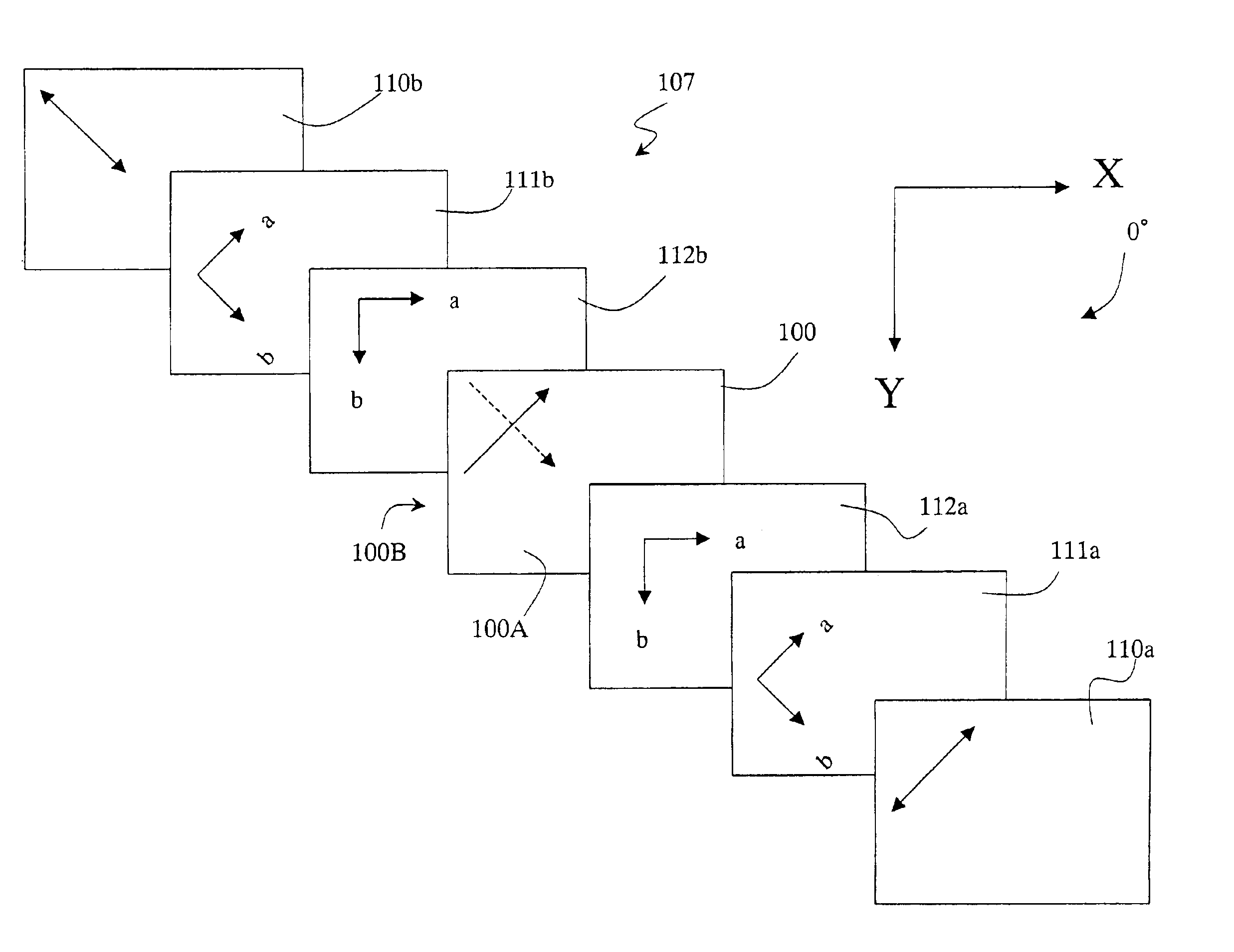
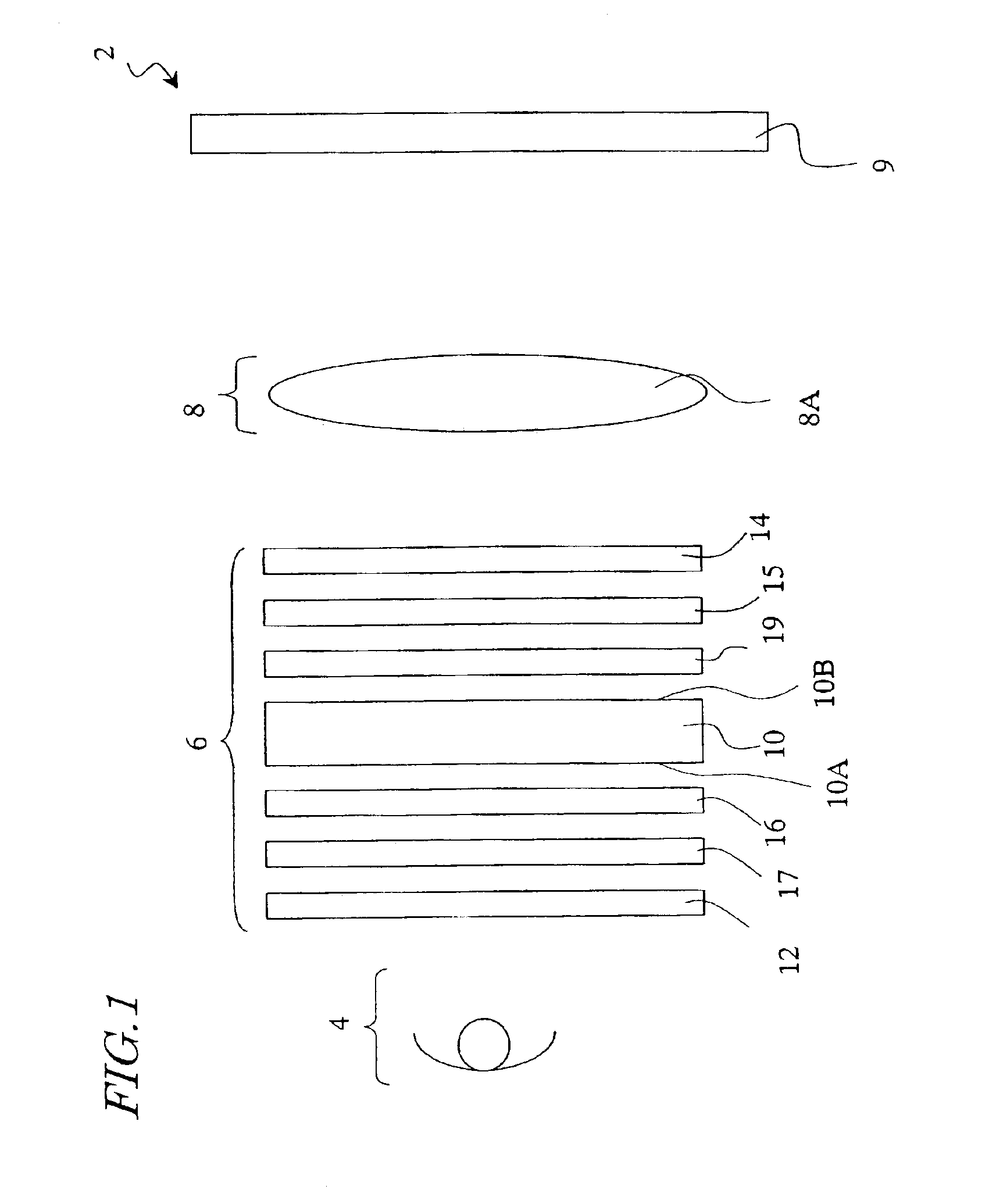
A projection type optical display system includes: a light source; at least one liquid crystal panel for modulating light that has been emitted from the light source; and a projection optical system for projecting the light that has gone out of the at least one liquid crystal panel. The liquid crystal panel includes: a liquid crystal layer; a first polarizer and a second polarizer, which are provided on the light incoming side and the light outgoing side of the liquid crystal layer, respectively; a first uniaxial optical compensator, which is provided between the liquid crystal layer and the first polarizer; a first biaxial optical compensator, which is provided between the first uniaxial optical compensator and the first polarizer; and a second biaxial optical compensator, which is provided between the liquid crystal layer and the second polarizer.

Description

BACKGROUND OF THE INVENTION[0001]1. Field of the Invention[0002]The present invention generally relates to an optical display system and more particularly relates to a projection type optical display system including a liquid crystal panel.[0003]2. Description of the Related Art[0004]A projection type optical display system may conduct a full-color display operation either by a three-panel method (i.e., with three liquid crystal panels used for the three primary colors of red, green and blue, respectively) or by a single-panel method (i.e., with just one liquid crystal panel used).[0005]A three-panel projection type optical display system includes: a color separation optical system for separating light, emitted from a white light source, into three light rays representing the three primary colors of red (R), green (G) and blue (B); three liquid crystal panels for modulating the R, G and B light rays in accordance with image information; a color synthesizing optical system for synthe...

Claims


Application Information

Patent Timeline
Patent Type & Authority Patents(United States)
IPC IPC(8): G02F1/1335G02B5/30G02B27/18G02F1/13G02F1/13363G03B21/00H04N9/31
CPCG02F1/133634H04N9/3197H04N9/3108
Inventor KUME, YASUHIROKURIHARA, TAKASHINAKANISHI, HIROSHI
Owner SHARP KK
Learn More