Non-contact measurement system for large airfoils

Inactive Publication Date: 2006-01-10
GENERAL ELECTRIC CO
View PDF18 Cites 28 Cited by
  • Summary
  • Abstract
  • Description
  • Claims
  • Application Information

AI Technical Summary

Benefits of technology

[0006]Briefly stated, the present invention integrates one or more commercially available non-contact optical sensors with a positioning system for moving the sensors over surface and edges of an airfoil which is held in a holding fixture in a position which is repeatable from one airfoil to the next. The airfoil is aligned in a standardized coordinate system for the purpose of relating accurate measurements of the airfoil's surface and edges to their design values. For airfoils which are smaller than the sensor's field of view, the airfoil is rotated about a rotary stage so both sides of the airfoil may be viewed by the sensor. For airfoils larger in size than the sensor's field of view, the sensors and the part are mo

Problems solved by technology

Because the shape of an airfoil is complex it has a critical bearing on the performance of an engine in which it is installed.
There are a number of problems associated with these inspection methods.
First, hard gauges are expensive, slow to manufacture and dedicated to a single airfoil shape.
Second, a significant amount of time is required to inspect an airfoil.
With complex surface shapes such as airfoils have, small errors in the use of

Method used


Image

  • Non-contact measurement system for large airfoils
  • Non-contact measurement system for large airfoils
  • Non-contact measurement system for large airfoils

Examples


Example

[0011]Corresponding reference numerals indicate corresponding parts throughout the several figures of the drawings.

DETAILED DESCRIPTION

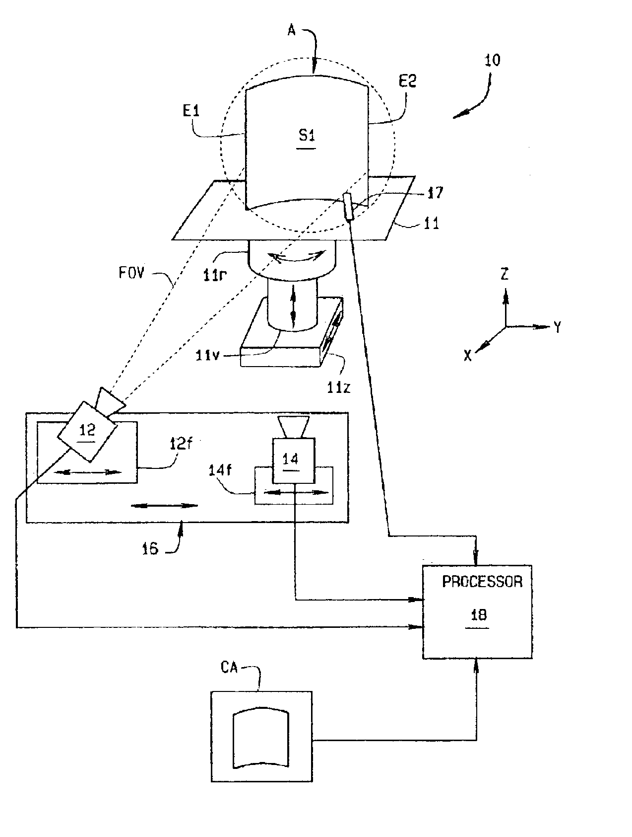
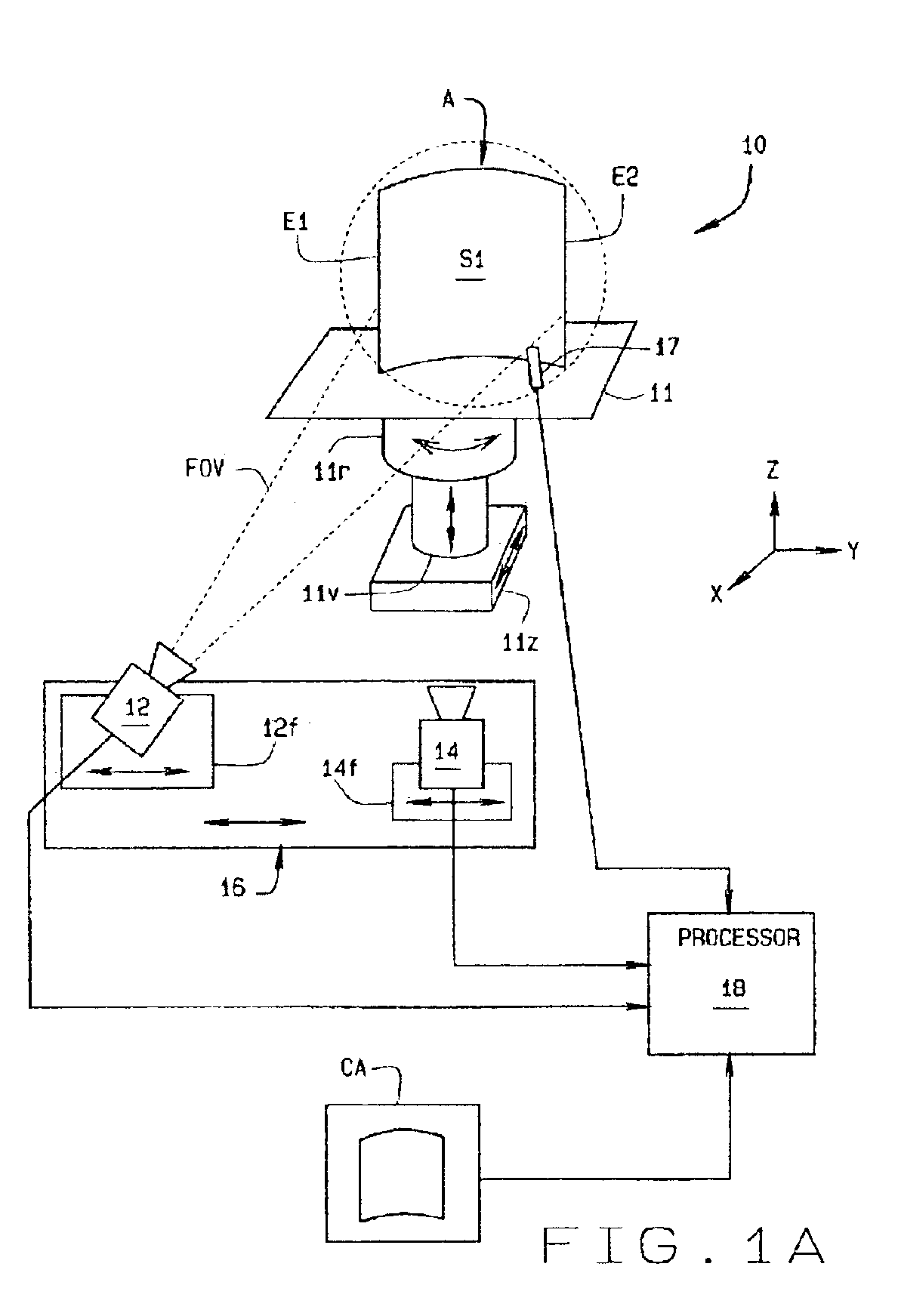
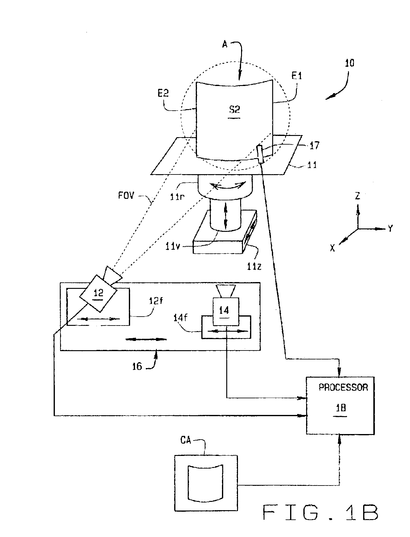
[0012]The following detailed description illustrates the invention by way of example and not by way of limitation. The description clearly enables one skilled in the art to make and use the invention, describes several embodiments, adaptations, variations, alternatives, and uses of the invention, including what is presently believed to be the best mode of carrying out the invention.

[0013]Referring to the drawings, a non-contact measurement system 10 of the present invention is used to measure a complex part shape such as an airfoil A to determine acceptability of the part. In the drawings, airfoil A is shown mounted on a precision root gripping fixture 11 which holds the airfoil in a desired fixed position which is repeatable from one airfoil to the next. In measuring the characteristics of the airfoil, it is important to both measure the surface fea...


PUM


Abstract

A non-contact measurement system employing a non-contact optical sensor and an edge detection sensor with a positioning system for moving the sensors over the surface and edges of a part (A) held in a predetermined, fixed position. The part is aligned in a co-ordinate system for obtaining accurate measurements of the part's surface (S) and edges (E). For parts smaller than the optical sensor's field of view, the part is rotated about an axis so both sides of the part are viewed by the sensor. If required, the part can also be shifted linearly along a horizontal axis (X) parallel to the sensor. For parts larger in size than the sensor's field of view, the part is moved along a vertical axis (Y) in predetermined segments so all of the part is exposed to viewing by the sensor.

Description

BACKGROUND OF INVENTION[0001]This invention relates to measuring systems, and more particularly to an optically based system for non-contact measurement of a part such as an airfoil having a complex part shape. Because the shape of an airfoil is complex it has a critical bearing on the performance of an engine in which it is installed. Airfoil shape is defined by a CAD definition in terms of sections, or a three dimensional (3D) surface characterized by a number of parameters which include contour, bow, and warp. Current methods inspecting airfoils utilize dedicated hard gauges or coordinate measuring machines (CMMs). Both methods determine whether or not an airfoil falls within drawing specified limits for contour, bow, twist and chord, as well as other parameters.[0002]There are a number of problems associated with these inspection methods. First, hard gauges are expensive, slow to manufacture and dedicated to a single airfoil shape. Manufacturing shops must store and perform regu...

Claims


Application Information

Patent Timeline
IPC IPC(8): G01B11/24
CPCG01B11/24
Inventor ISAACS, RALPH GERALDJANNING, JOHN CHARLESLITTLE, FRANCIS HOWARDREINHARDT, JAMES ROBERTROSS, JOSEPH BENJAMIN
Owner GENERAL ELECTRIC CO
Why Eureka
Try Eureka