Cross-bar switch system with redundancy

a switch system and crossbar switch technology, applied in the field of computer systems, can solve the problems of faulty cpu being detached from the system, no longer connecting the computer cpus and memory or the node, and the switch cannot be allowed to degrade, etc., to achieve the effect of rapid recovery of the system and low cos

Inactive Publication Date: 2006-01-10
NEC CORP
View PDF13 Cites 5 Cited by
  • Summary
  • Abstract
  • Description
  • Claims
  • Application Information

AI Technical Summary

Benefits of technology

[0008]Accordingly, an object of the present invention is to provide a crossbar switch system in which rapid recovery of the system can be achieved at low cost when a crossbar switch fails.

Problems solved by technology

In the prior art there are the following problems, if a crossbar switch develops a failure, the switch cannot be allowed to degrade as in the manner of a CPU or memory, etc.
That is, a faulty CPU is detached from the system when the system is restarted.
If a faulty crossbar switch is allowed to degrade, however, the computer CPUs and memory or the nodes can no longer be connected.
As a consequence, the system will not operate.
Thus, a problem with the conventional crossbar switch is that system recovery cannot be achieved until the faulty parts of the crossbar switch are replaced.
The result is prolonged system downtime.
Though a system in which all of the crossbar switch components are provided with redundancy, i.e., duplicated in order to avoid the foregoing problem is available, the system is high in cost and impractical.

Method used


Image

  • Cross-bar switch system with redundancy
  • Cross-bar switch system with redundancy
  • Cross-bar switch system with redundancy

Examples


Embodiment Construction

[0036]A mode for carrying out the present invention will be described below.

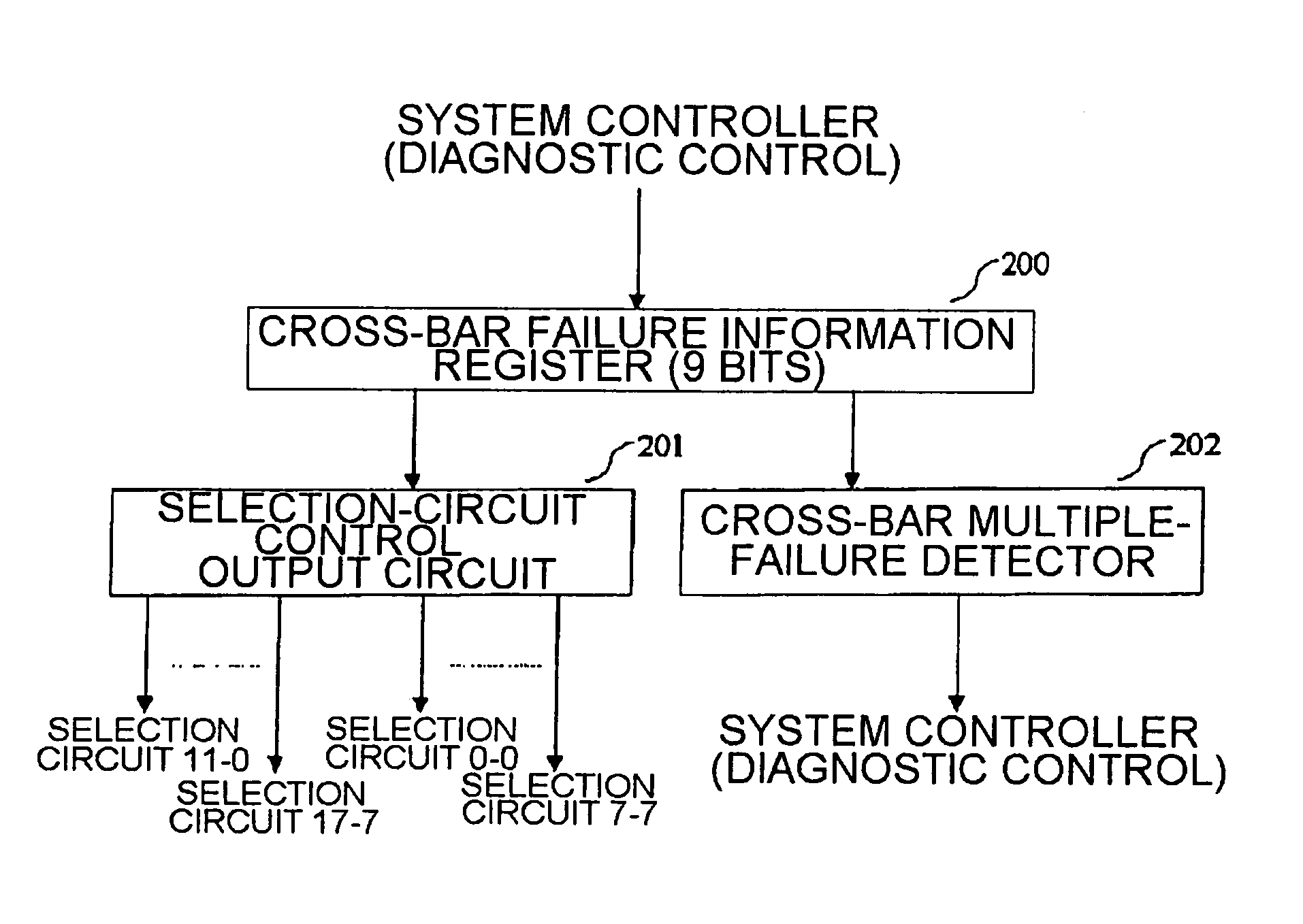
[0037]According to an embodiment of the crossbar the crossbar switch system according to the present invention, the system is provided with N+1 crossbar switches of which N are required and one is redundant. If a failure processing circuit recognizes failure of a cross-bar switch when such a failure occurs in the system, the failure processing circuit controls selection circuits, which are provided at inputs and outputs of the cross-bar switches, after the system is restarted, to thereby take the faulty cross-bar switch out of service and place the redundant cross-bar switch in service.

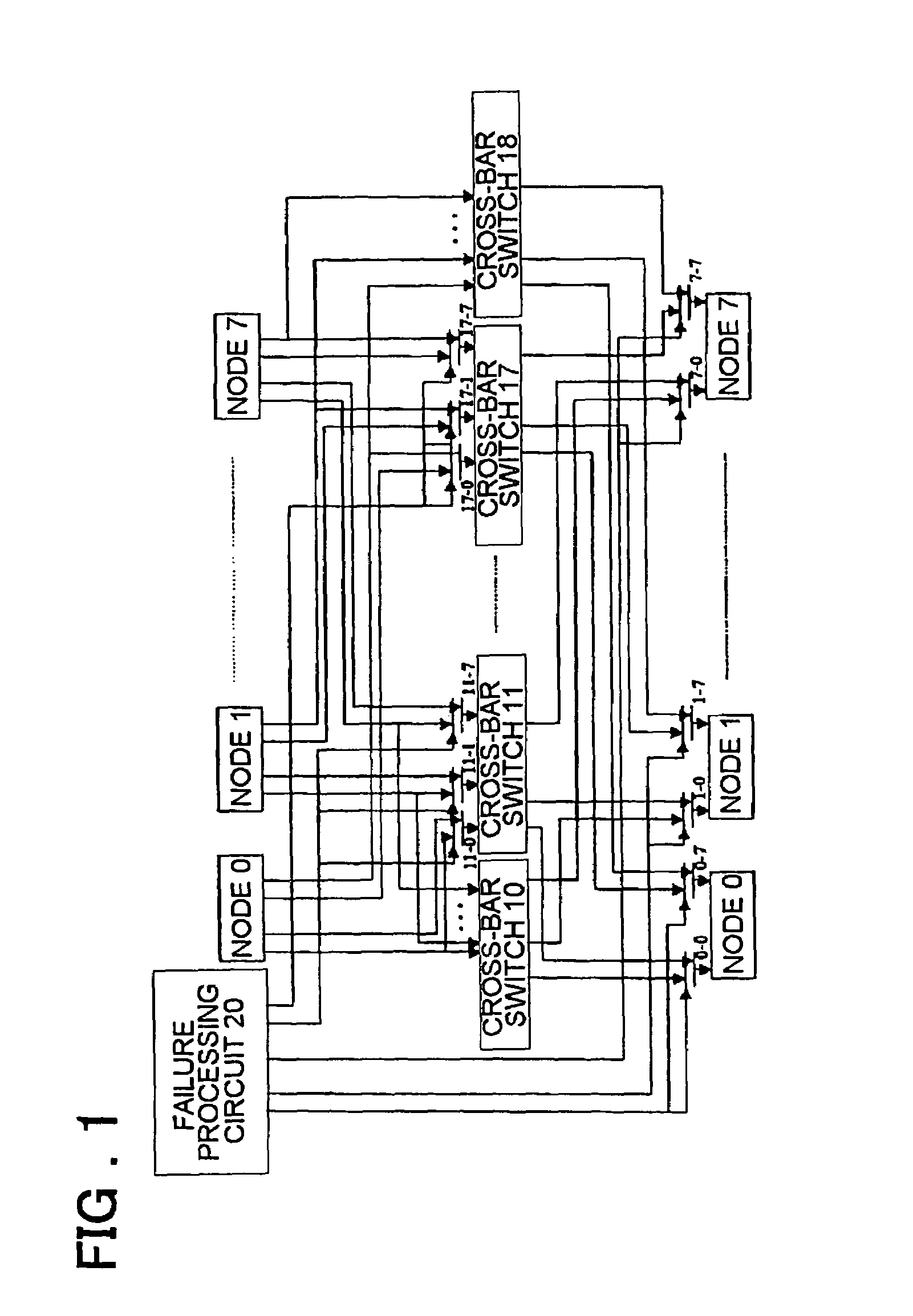
[0038]More specifically, according to a preferred mode for carrying out the present invention, a cross-bar switch system has first to (N+1)th cross-bar switches wherein one cross-bar switch is provided in addition to N cross-bar switches (N=8 holds in FIG. 1) required for connecting of nodes among first to Mth (M=8 in FIG. 1) ...


PUM


Abstract

A crossbar switch system with redundancy has N+1 cross-bar switches. A first cross-bar switch has first outputs of each of a plurality of nodes applied to N input terminals thereof, an (N+1)th cross-bar switch has Nth outputs of each of the nodes applied to N input terminals thereof, and second to Nth (Ith) cross-bar switches each have first to Nth selection circuits, which are provided at respective input terminals thereof, to each of which are input mutually adjacent (I−1)th and Ith outputs among outputs of each of the nodes. Each (Jth) node has N selection switches, which are provided at input terminals thereof, to each of which are input Jth outputs of two mutually adjacent cross-bar switches among the first to (N+1)th cross-bar switches. In response to a selection control signal output from a failure processing circuit that executes crossbar switch failure processing, each of the selection circuits selects and outputs one of its two inputs.

Description

FIELD OF THE INVENTION[0001]This invention relates to a computer system and, more particularly, to a system in which crossbar switches for connecting CPUs and memory of a computer or for connecting the nodes in a computer system constituted by multiple nodes are provided with redundancy.BACKGROUND OF THE INVENTION[0002]In modern computer systems, crossbar switches are used to switchingly connect the CPUs and memory of a computer, for example, or the nodes in a computer system constituted by multiple nodes. Crossbar switches are constructed on a plurality of LSI chips or cards or on a single LSI chip, which includes a plurality of crossbar switch blocks, in accordance with the bit slice or byte slice, etc.SUMMARY OF THE DISCLOSURE[0003]In the prior art there are the following problems, if a crossbar switch develops a failure, the switch cannot be allowed to degrade as in the manner of a CPU or memory, etc. That is, a faulty CPU is detached from the system when the system is restarted...

Claims


Application Information

Patent Timeline
Patent Type & Authority Patents(United States)
IPC IPC(8): H04L12/28H04L12/56G06F11/20G06F11/00G06F13/00G06F15/16G06F15/173H04Q3/52
CPCH04L49/552H04L49/101
Inventor SUZUKI, KATSUYUKI
Owner NEC CORP
Why Eureka
Try Eureka